LiftMaster RSL12U RSL12U Troubleshooting Guide Manual - Page 22
Models Sl585u And Sl595u (three Phase), Power
 |
View all LiftMaster RSL12U manuals
Add to My Manuals
Save this manual to your list of manuals |
Page 22 highlights
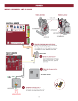
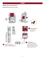
POWER MODELS SL585U AND SL595U (THREE PHASE) CONTROL BOARD BIPART DELAY 4 2 6 OPEN LEFT OPEN 8 RIGHT HANDING MODEL SL585U CONTROL BOARD POWER BOARD MODEL SL595U CONTROL BOARD POWER BOARD JUNCTION BOX AC POWER SWITCH JUNCTION BOX COMM LINK BA CLASS 2 SUPPLY 24 VAC 500 mA MAX GND ANTENNA CURRENT MOTOR DRIVE SENSOR ID RESET RPM & LIMITS ALARM EXP. BOARD 24 VAC IN POWER BOARD THREE PHASE J9 12V 12V J12 MOTOR CURRENT J14 (BLACK) L1 J1 (WHITE) L2 J2 (PURPLE) L3 J3 LINE IN TRANSFORMER 240/575V 208V ORANGE RED PURPLE WHITE COMM 24V J6 J11 480V BRAKE J8 J7 J10 J13 J4 J5 480V 240V/208V 575V 4 Blue Yellow White COM 120 Red Orange 208 24 VAC 240 Purple 460 3.15A FUSE TRANSFORMER Fuse To configure the motor for 208V, swap the orange and red wires and plug motor into the 208V / 240V position. Check the transfomer and control board.* Check the blue and yellow 24 VAC IN wires at the control board. The voltage should be about 21-28 Vac. If the voltage is NOT 21-28 Vac, replace the transformer. If the voltage IS 21-28 Vac, replace the fuse. If the fuse is good, replace the control board. 3 Check the power board.* Check the following transformer wires on the power board: 208V Applications: Check the white and red wires, voltage should be 208 Vac 240V Applications: Check the white and orange wires, voltage should be 240 Vac 480V Applications: Check the white and purple wires, voltage should be 480 Vac If the voltage is not correct, replace the power board. SWITCH AC POWER SWITCH 2 Check the AC power switch. Is it ON? L3 Purple L2 White L1 Black Purple White Black * Green JUNCTION BOX 1 Check the incoming power.* Check breaker first, then check wiring coming into operator. The voltage should be 208, 240, or 480 Vac depending on the application. NCOMING POWER 21
-
 1
1 -
2
-
3
-
4
-
5
-
6
-
7
-
8
-
9
-
10
-
11
-
12
-
13
-
14
-
15
-
16
-
 17
17 -
 18
18 -
 19
19 -
 20
20 -
 21
21 -
 22
22 -
 23
23 -
 24
24 -
 25
25 -
 26
26 -
 27
27 -
28
-
29
-
30
-
31
-
32
-
33
-
34
-
35
-
36
 |
 |
