LiftMaster RSL12U RSL12U Troubleshooting Guide Manual - Page 4
Basic Troubleshooting, Multi-meters
 |
View all LiftMaster RSL12U manuals
Add to My Manuals
Save this manual to your list of manuals |
Page 4 highlights
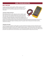
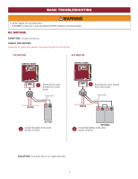
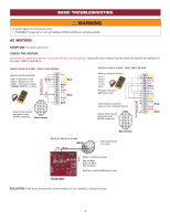
BASIC TROUBLESHOOTING MULTI-METERS The image is an example of a generic multimeter. LiftMaster currently has no intended affiliations with this multi-meter manufacturer. This is not an endorsement for this particular meter model. When shopping for a meter, look for a meter able to fit in a shirt pocket or clip on a belt. A meter with an audio signal (buzzer) for continuity checks is recommended. CHECKING OHMS/CONTINUITY When checking the operation of a switch, select the ohm mode on multimeter. (The ohm symbol is ). Make sure the test leads are plugged into the correct sockets for reading ohms. If there is more than one setting in the ohm section of the meter, select the one with the audio signal. To test a limit switch, connect one test lead to the Common prong and the other to the Normally Closed prong. The meter should read 0 resistance or very low resistance. The electricity is flowing from the Common prong to the Normally Closed prong. This demonstrates continuity. Activate the switch, the meter will read Infinite resistance or no continuity. The wires inside the switch are no longer touching between the Common prong and the Normally Closed prong. Move the test lead from Normally Closed to Normally Open. While the activation arm is not pressed, the meter should read open circuit, demonstrating no continuity. Activating the arm should read 0 resistance, demonstrating continuity. The procedure is called a "Continuity Check" and is used to check for a continuous flow of electricity. CHECKING VOLTAGE A multimeter may have several settings for checking voltages. The number associated with each setting is the maximum voltage able to be read. A meter may be damaged if connected to a higher voltage than selected. Either AC or DC must be selected prior to testing any circuit. AC stands for alternating current and DC stands for direct current. AC is usually the incoming line voltage, i.e. 115 Vac, 460 Vac and so on. 24 Vac is also found in the control circuit of an operator. DC is usually a power source from a battery or the control voltage in a logic board. Set the meter to VOLTS AC at the lowest setting which is still higher than the expected voltage. If 115 Vac is expected and the meter has 10 Vac, 50 Vac, 250 Vac and 1000 Vac, turn the dial to 250 Vac. Some meters have only one Vac choice and the meter can automatically adjust for the voltage received (auto scaling). 3
-
 1
1 -
 2
2 -
 3
3 -
 4
4 -
 5
5 -
 6
6 -
 7
7 -
 8
8 -
 9
9 -
 10
10 -
11
-
12
-
13
-
14
-
15
-
16
-
17
-
18
-
19
-
20
-
21
-
22
-
23
-
24
-
25
-
26
-
27
-
28
-
29
-
30
-
31
-
32
-
33
-
34
-
35
-
36
 |
 |
