LiftMaster RSL12UL Owners Manual - English French - Page 25
OPERATION, Control Board Overview - troubleshooting
 |
View all LiftMaster RSL12UL manuals
Add to My Manuals
Save this manual to your list of manuals |
Page 25 highlights
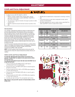
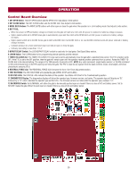
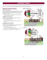
OPERATION Control Board Overview 1 SET OPEN Button: The SET OPEN button sets the OPEN limit. See Adjust Limits section. 2 SET CLOSE Button: The SET CLOSE button sets the CLOSE limit. See Adjust Limits section. 3 MOVE GATE Buttons: The MOVE GATE buttons will either open or close the gate when the operator is in Limit setting mode. See Adjust Limits section. 4 BATT FAIL: l When AC power is OFF and battery voltage is critically low the gate will latch at a limit until AC power is restored or batteries voltage increases. l Option select switch set to OPEN forces gate to automatically open and then latch at the OPEN limit until AC power is restored or battery voltage increases. l Option select switch set to CLOSE forces gate to latch at CLOSE limit if at CLOSE limit or on next CLOSE command until AC power restored or battery voltage increases. l Constant pressure on a hard command input overrides to open or close the gate. l Critically low battery is less than 11.5 V 5 BIPART DELAY Switch: The LOCK/BIPART DELAY switch is used only for dual gates. See Bipart Delay section. 6 LEARN Button: The LEARN button is for programming remote controls and the network. 7 TIMER-TO-CLOSE dial: The TIMER-TO-CLOSE (TTC) dial can be set to automatically close the gate after a specified time period. The TTC is factory set to OFF. If the TTC is set to the OFF position, then the gate will remain open until the operator receives another command from a control. Rotate the TIMER-TOCLOSE dial to the desired setting. The range is 0 to 180 seconds, 0 seconds is OFF. NOTE: Any radio command, single button control, or CLOSE command on the control board prior to the TTC expiring will close the gate. The TTC is reset by any signals from the open controls, loops, close edges, and close photoelectric sensors (IR's). 8 REVERSAL FORCE dial: The REVERSAL FORCE dial fine tunes the force. See Force Adjustment section. 9 TEST BUTTONS: The TEST BUTTONS will operate the gate (OPEN, STOP and CLOSE). 10 STATUS LEDs: The STATUS LEDs indicate the status of the operator. See Status LED Chart in the Troubleshooting section. 11 DIAGNOSTICS Display: The diagnostics display will show the operator type, firmware version, and codes. The operator type will display as "SL" followed by a "12" which indicates the operator type as RSL12UL. The firmware version will show after the operator type, example "1.2". 12 BACKDRIVE Switch: Set to MANUAL will allow the gate to be manually pushed open or closed if there is a loss of AC and battery power. Set to SECURE makes the gate difficult to push open or closed if there is a loss of AC and battery power. 25
-
 1
1 -
2
-
3
-
4
-
5
-
6
-
7
-
8
-
9
-
10
-
11
-
12
-
13
-
14
-
15
-
16
-
17
-
18
-
19
-
 20
20 -
 21
21 -
 22
22 -
 23
23 -
 24
24 -
 25
25 -
 26
26 -
 27
27 -
 28
28 -
 29
29 -
 30
30 -
31
-
32
-
33
-
34
-
35
-
36
-
37
-
38
-
39
-
40
-
41
-
42
-
43
-
44
-
45
-
46
-
47
-
48
 |
 |