LiftMaster T T LOGIC VERSION 2 Manual - Page 15
Wiring Type Program Settings
 |
View all LiftMaster T manuals
Add to My Manuals
Save this manual to your list of manuals |
Page 15 highlights
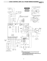
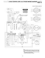
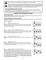
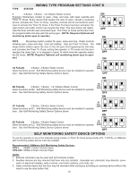
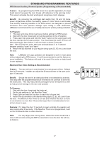
Refer to printed circuit board illustration on page 20 for all component locations. Before Programming the logic board, set the operators open and close limits. LEDs on the logic board are provided to assist setting the limits. As each limit is activated the corresponding LED will light up. The abbreviations are Open Limit Switch (OLS), Close Limit Switch (CLS) and Sensing Limit Switch (SLS). Refer to page 7 for limit switch adjustment instructions. Logic Control Pushbuttons Open, Close, Stop Open, Close and Stop buttons are mounted directly on the Logic Control board. This will provide easy programming ability and door control at the electrical box. Either the stop control or a jumper must be wired between terminals 4 and 5 for the on board push buttons to function. WIRING TYPE PROGRAM SETTINGS Determine wiring mode: There are many wiring modes available on the Logic Board. Read the descriptions of the different wiring types to determine which setting will be correct for each application. Set the dip switches to the desired wiring mode: Adjust the 4 dip switches on the logic board to match the settings for the desired wiring type. The dip switches are shown in the picture TYPE STATION ON ON C2 3 Button, 3 Button Radio Control Function: Momentary contact to open and stop with constant pressure to close, C2 open override plus wiring for sensing device to reverse. Programmable mid stop available with this wiring type. 1 2 3 4 OFF ON ON B2 3 Button, 1 Button, 1 & 3 Button Radio Control Function: Momentary contact to open, close and stop, plus wiring for sensing B2 device to reverse and auxiliary devices to open and close with open override. Programmable mid stop available with this wiring type. 1 2 3 4 OFF ON D1 2 Button, 3 Button Radio Control ON Function: Constant pressure to open and close with wiring for sensing device to D1 stop. 1 2 3 4 OFF E2 3 Button Radio Control Function: Momentary contact to open with override and constant pressure to close. Release of close button will cause door to reverse (roll-back feature) plus wiring for sensing device to reverse. ON ON E2 1 2 3 4 OFF TS 3 Button, 1 Button, 1 & 3 Button Radio Control ON Function: Momentary contact to open, close, and stop with open override and ON Timer To Close. Every device that causes door to open, including a reversing device, activates the Timer To Close. Auxiliary controls can be connected to open TS input to activate the Timer To Close. If the timer has been activated, the open button and radio control can recycle the timer. The stop button will deactivate the Tim er To Close until the next command input. The Timer To Close will function from 1 2 3 4 OFF the programmable mid-stop with this wiring type. (NOTE: Requires Optional self monitoring photo eyes to operate.) 15
-
 1
1 -
2
-
3
-
4
-
5
-
6
-
7
-
8
-
9
-
 10
10 -
 11
11 -
 12
12 -
 13
13 -
 14
14 -
 15
15 -
 16
16 -
 17
17 -
 18
18 -
 19
19 -
 20
20 -
21
-
22
-
23
-
24
-
25
-
26
-
27
-
28
 |
 |