LiftMaster T T LOGIC VERSION 2 Manual - Page 2
Table Of Contents, Packing List - trolley assembly
 |
View all LiftMaster T manuals
Add to My Manuals
Save this manual to your list of manuals |
Page 2 highlights
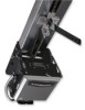
Before attempting to install, operate or maintain the operator, you must read and fully understand this manual and follow all safety instructions. These instructions are intended to highlight certain safety related issues. These instructions are not intended to be comprehensive. Because each application is unique, it is the responsibility of the purchaser, designer, installer and end user to ensure that the total door system is safe for its intended use. TABLE OF CONTENTS SPECIFICATIONS Packing List 2 Motor Specification 3 Electrical Specifications 3 Mechanical Specifications 3 Safety Specifications 3 Weights & Dimensions 3 PREPARATION Track Assembly 4 Powerhead Attachment 4 Trolley Carriage/ Chain Attachment 4 INSTALLATION INSTRUCTIONS Mounting Header Bracket 5 Mounting Operator 5 Operator Support 6 Straight Arm Attachment 6 ENTRAPMENT PROTECTION ACCESSORIES Sensing Edges & Photo Eyes 7 LIMIT SWITCH ADJUSTMENT Limit Location 7 Adjustment 7 POWER & CONTROL WIRING Safety Warnings 8 Power Wiring 9 Ground Wiring 9 Control Station Wiring 9 Radio Controls 9 Mounting Instructions 9 Optional Control Mounting 9 Optional Control Wiring 28 EMERGENCY DISCONNECT SYSTEM Disconnecting 10 Connecting 10 BRAKE ADJUSTMENT Brake Parts 11 CLUTCH ADJUSTMENT Clutch Parts 11 Clutch Adjustment 11 WIRING DIAGRAMS 1 PH Control Connections 12 3 PH Control Connections 12 1 PH Wiring 13 3 PH Wiring 14 STANDARD PROGRAMMING Wiring Type 15 & 16 Self Monitoring Safety Devices 16 RPM Sensor 17 Maximum Run Timer 17 Maintenance Alert System 18 OPTIONAL PROGRAMMING Mid Stop 18 Timer to Close 19 Red Green Warning Lights 19 Board Illustration 20 REPLACEMENT PARTS & MAINTENANCE Trouble Shooting Guide 21 & 22 Maintenance Schedule 23 Customer Service Contact Information 23 Electrical Box parts 24 & 25 Chassis Parts 26 & 27 PACKING LIST Before beginning your installation check that all components were supplied and received undamaged. PART # 01-17278 02-103L 10-10203 10-10204 10-10205 11-10130 11-10197 19-41ML 40-15259 40-55 75-10174 HARDWARE KIT (K77-13821) DESCRIPTION OWNERS MANUAL 3 BUTTON STATION DOOR CURVED ARM DOOR BRACKET TRACK END BRACKET PIVOT SHAFT TAKE-UP BOLT MASTER LINK, #41 LABEL, MAINTENANCE ALERT LABEL, TROLLEY CAUTION FRONT IDLER ASSEMBLY QTY. 1 1 1 1 1 1 1 2 1 2 1 PART # 75-10214 75-10259 75-17942 82-HN38-12 82-HN38-16 82-RN31-26 84-FN-31 84-FN-38 84-LH-38 85-LS-38 86-CP045-108 DESCRIPTION DOOR ARM ASSEMBLY TRACK SPACER ASSEMBLY TROLLEY SLIDER HEX BOLT, 3/8-16 X 3/4" LONG HEX BOLT, 3/8-16 X 1" LONG CARRIAGE BOLT, 5/16-18 X 2-1/2" FLANGE NUT, 5/16-18 FLANGE NUT, 3/8-16 LOCKNUT, 3/8-16 LOCKWASHER, 3/8" COTTERPIN, 9/64 X 1-1/2" LONG QTY. 1 2 1 10 3 2 2 12 1 3 2 2
-
 1
1 -
 2
2 -
 3
3 -
 4
4 -
 5
5 -
 6
6 -
 7
7 -
 8
8 -
9
-
10
-
11
-
12
-
13
-
14
-
15
-
16
-
17
-
18
-
19
-
20
-
21
-
22
-
23
-
24
-
25
-
26
-
27
-
28
 |
 |
