Lowrance HDS-7 Gen2 Touch Installation Manual - Page 25
Micro-C T junctions - operational manual
 |
View all Lowrance HDS-7 Gen2 Touch manuals
Add to My Manuals
Save this manual to your list of manuals |
Page 25 highlights
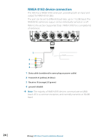
In smaller NMEA 2000 systems, the power connection may be made anywhere in the system, For larger systems introduce power at a central point in the backbone to 'balance' the voltage drop of the network. Use a power cable without termination. ¼¼ Note: When joining a NMEA 2000 network with a Simrad SimNet network, it is important that you do not introduce power to both. ¼¼ Note: Do not connect the power cable to the same terminals as the autopilot computer, pulse radar, bow thruster or other high current devices - the network may be affected by voltage drop when these devices are operated. Avoid connection to the engine starting batteries where possible. The following diagram demonstrates a typical small NMEA 2000 network: 1 2 3 5 _+ 12 V DC 6 T 9 7 8 1 GPS antenna 2 HDS Display 3 Broadband radar interface 4 SonicHub 5 'Drop' cables (should not exceed 6m (20') each) 6 Power cable 7 Micro-C T junctions 8 Backbone 9 Micro-C terminator (one male, one female) 4 T 9 Wiring | HDS Gen2 Touch Installation Manual | 23
-
 1
1 -
2
-
3
-
4
-
5
-
6
-
7
-
8
-
9
-
10
-
11
-
12
-
13
-
14
-
15
-
16
-
17
-
18
-
19
-
 20
20 -
 21
21 -
 22
22 -
 23
23 -
 24
24 -
 25
25 -
 26
26 -
 27
27 -
 28
28 -
 29
29 -
 30
30 -
31
-
32
-
33
-
34
-
35
-
36
-
37
-
38
-
39
-
40
 |
 |
