MSI 661FM3-V User Guide
MSI 661FM3-V - Motherboard - Micro ATX Manual
 |
UPC - 816909007435
View all MSI 661FM3-V manuals
Add to My Manuals
Save this manual to your list of manuals |
MSI 661FM3-V manual content summary:
- MSI 661FM3-V | User Guide - Page 1
if not installed and used in accordance with the instruction manual, may cause harmful interference to radio communications. Operation limits. VOIR LA NOTICE D'NSTALLATION AVANT DE RACCORDER AU RESEAU. Micro-Star International MS-7103 This device complies with Part 15 of the FCC Rules. Operation - MSI 661FM3-V | User Guide - Page 2
document is the intellectual property of MICRO-STAR INTERNATIONAL. We take every care . Microsoft® is a registered trademark of Microsoft Corporation. Windows® 98/2000/NT/XP are registered trademarks of Microsoft Corporation with chipsets SiS ® 661FX/648FX/648 & SiS ® 964/964L V1.1 Add one chipset - MSI 661FM3-V | User Guide - Page 3
1. Always read the safety instructions carefully. 2. Keep this User Manual for future reference. 3. Keep this equipment away shock. 11. If any of the following situations arises, get the equipment checked by a service personnel: - The power cord or plug is damaged. - Liquid has penetrated into the - MSI 661FM3-V | User Guide - Page 4
Table of Content English 1 Deutsch 15 Français 31 47 61 75 iv - MSI 661FM3-V | User Guide - Page 5
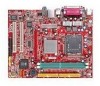
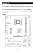
-V/648M3-V/648FM3-V Series (MS-7103 v1.X) micro ATX mainboard. The 661FM3-V/661GM3-V/648M3-V/648FM3-V Series is based on SiS ® 661FX/GX/648FX/648 & SiS ® 964/964L chipsets for optimal system efficiency. Designed to fit the advanced Intel ® Pentium ® 4/Celeron D processors in 775 pin package, the - MSI 661FM3-V | User Guide - Page 6
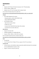
information about CPU, please visit http://www.msi.com.tw/program/products/mainboard/mbd/pro_mbd_cpu_support.php ) Chipset l SiS ® 648FX/648/661GX/FX Chipset - Integrated graphic controller (661FX/661GX only) - Support DDR333/400 SDRAM l SiS ® 964/964L Chipset - High Definition Audio interface - MSI 661FM3-V | User Guide - Page 7
requirement LAN (Optional) l RealtekR 8201CL - Integrated Fast Ethernet PHY. - Supports 10Mb/s, 100Mb/s. - Compliance with PCI 2.2. - Supports ACPI Power Management. BIOS l 4Mb l Provides DMI2.0, WfM2.0, WOL, WOR, chassis intrusion, and SMBus for system management Dimension l Micro-ATX Form - MSI 661FM3-V | User Guide - Page 8
LAN USB Ports Keyboard COM port VGA port (Optional, for 661FX/GX only) USB Ports Line In Line Out Mic In Hardware Setup This chapter tells you how to install the CPU, memory modules, and expansion cards, as well as how to setup the jumpers on the mainboard. It also provides the instructions - MSI 661FM3-V | User Guide - Page 9
the clips to release the CPU, then press down the CPU with your index finger to allow the whole module to be installed onto the CPU socket. 10. The CPU is installed well on the CPU socket. 11. Visually inspect if the CPU is seated well into the socket, then remove the CPU Clip with 2 fingers. Then - MSI 661FM3-V | User Guide - Page 10
to lift up the CPU. Memory The mainboard provides two 184-pin unbuffered DDR333/DDR400 DDR SDRAM, and supports the memory size up to 2GB. To operate properly, at least one DIMM module must be installed. (For the updated supporting memory modules, please visit http://www.msi.com.tw/program/products - MSI 661FM3-V | User Guide - Page 11
supply firmly into the connector. 3.3 V 1 11 ATX 12V Power Connector: JPW1 GND 12 This 12V power connector is used to provide power to the CPU. 12V 34 5V 5V -5V GND GND GND P the warning, you must enter the BIOS setting and clear the status. R CD-In Connector: CD_IN1 GND The connector is - MSI 661FM3-V | User Guide - Page 12
system fan) support system cooling fan with +12V. They support three-pin/four should be connected to GND. MSI Reminds You... Always consult the vendors for proper CPU cooling fan. IDE Connectors: IDE1 can also connect a Master and a Slave drive. MSI Reminds You... If you install two hard disks on - MSI 661FM3-V | User Guide - Page 13
connector allows you to connect to the front panel audio and is compliant with Intel ® Front Panel I/O Connectivity Design Guide. AUD_MIC_BIAS AUD_FPOUT_R AUD_MIC NC AUD_FPOUT_L 9 1 10 2 AUD_RET_L KEY AUD_RET_R AUD_GND AUD_VCC MSI Reminds You... If you do not want to connect to the - MSI 661FM3-V | User Guide - Page 14
dual high-speed Serial ATA interface ports. The ports support 1st generation Serial ATA data rates of 150MB/s and 5 RXN 7 GND PIN SIGNAL 2 TXP 4 GND 6 RXP SATA2 71 SATA1 MSI Reminds You... Please do not fold the serial ATA cable in a 90-degree instructions below to clear the data: 10 - MSI 661FM3-V | User Guide - Page 15
MSI Reminds You... for the graphics controller to directly access main memory. The mainboard supports 4x AGP card. PCI (Peripheral Component Interconnect) Slots The PCI slots the expansion card, such as jumpers, switches or BIOS configuration. PCI Interrupt Request Routing The IRQ, abbreviation - MSI 661FM3-V | User Guide - Page 16
this menu for basic system configurations, such as time, date etc. Advanced BIOS Features Use this menu to setup the items of Award special enhanced features. This entry appears if your system supports PnP/PCI. H/W Monitor This entry shows the status of your CPU, fan, warning for overall system - MSI 661FM3-V | User Guide - Page 17
menu to set BIOS setting Password. Save & Exit Setup Save changes to CMOS and exit setup. Exit Without Saving Abandon all changes and exit setup. Frequency/Voltage Control Current CPU Clock It shows the current clock of CPU. Read-only. Adjust DDR Memory Frequency When it is set to [Manual] in High - MSI 661FM3-V | User Guide - Page 18
minimize the electromagnetic interference (EMI). Spread Spectrum When the motherboard's clock generator pulses, the extreme values (spikes) of pulses are reduced to flatter curves. If you do not have any EMI problem, leave the setting at Disabled for optimal system stability and performance. But if - MSI 661FM3-V | User Guide - Page 19
Einleitung Danke, dass Sie das 661FM3-V/661GM3-V/648M3-V/648FM3-V Series (MS-7103 v1.X) Mikro ATX Mainboard gewählt haben. Das 661FM3-V/661GM3-V/648M3-V/648FM3-V Series basiert auf den SiS ® 661FX/GX/648FX/648 und SiS ® 964/964L Chipsätzen und ermöglicht so ein optimales und effizientes System. - MSI 661FM3-V | User Guide - Page 20
besuchen Sie bitte http://www.msi.com.tw/program/products/mainboard/mbd/pro_mbd_cpu_support.php ) Chipsatz l SiS ® 648FX/ 648/661FX/661GX Chipsatz - Integrierter Grafikkontroller (nur 661FX/661GX) - Unterstützt DDR333/400 SDRAM l SiS ® 964/964L Chipsatz - High Definition Audio Schnittstelle - 8 USB - MSI 661FM3-V | User Guide - Page 21
Fast Ethernet PHY. - Unterstützt 10Mb/s und 100Mb/s. - Erfüllt die Anforderungen nach PCI 2.2. - Unterstützt ACPI Stromsparfunktionalität. BIOS l 4Mb l Bietet zur Systemverwaltung DMI2.0, WfM2.0, WOL, WOR, Warnungmeldung nach Öffnen des Gehäuses und SMBus Abmessungen l Micro-ATX Form Faktor - MSI 661FM3-V | User Guide - Page 22
Anschlüsse: Mouse Parallel Port (Optional) LAN USB Ports Line In Line Out Mic In Keyboard COM port VGA port (Optional, for 661FX/GX only) USB Ports Hardware Setup Dieses Kapitel informiert Sie darüber, wie Sie die CPU, Speichermodule und Erweiterungskarten einbauen, des weiteren dar - MSI 661FM3-V | User Guide - Page 23
zwei Markierungen am Pin 1 (die Dreiecke auf CPU und CPU Clip), und verwenden Sie den CPU Clip um die CPU aufzunehmen, indem Sie die Klammern an beiden Seiten zur stets abgedeckt, um die Sockelpins zu schützen, bis Sie die CPU einbauen. 6. Entfernen Sie die Kappe von der Seite des Hebelgelenks her - MSI 661FM3-V | User Guide - Page 24
Sie Punkt 8 die Details) und drücken Sie den Clip auf, um die CPU herauszuheben. Speicher Das Mainboard bietet Platz für zwei ungepufferte 184-Pin DDR333 / DDR400 ützten Speichermodule zu erhalten, besuchen Sie bitte http://www.msi.com.tw/program/products/mainboard/mbd/pro_mbd_trp_list.php) Setzen - MSI 661FM3-V | User Guide - Page 25
und die Pins ausgerichtet sind. Drücken Sie dann den Netzteilstecker fest in den Steckersockel. ATX 12V Stromanschluss: JPW1 GND 12 GND Dieser 12V Stromanschluss wird verwendet, um die CPU mit 12V 12V Strom zu versorgen. . 34 Anschluss des Diskettenlaufwerks: FDD1 Das Mainboard verfügt - MSI 661FM3-V | User Guide - Page 26
System zeichnet diesen Zustand auf. Um die Warnmeldung zu löschen, müssen Sie das BIOS aufrufen und dort den Status zurücksetzen. CD-Eingang: CD_IN1 Hier kann das Audiokabel mit GND verbunden werden. MSI weist darauf hin... Bitten Sie stets Ihren Händler um Hilfe bei der Auswahl des geeigneten - MSI 661FM3-V | User Guide - Page 27
werden. IDE2 kann ebenfalls je ein Master- und ein Slave- Laufwerk verwalten. MSI weist darauf hin... Verbinden Sie zwei Laufwerke über ein Kabel, müssen Sie das "Intel Front Panel I/O Connectivity Design System LED System Schalter Guide". . JFP1 System LED 1 2 Lautsprecher 7 8 JFP2 23 - MSI 661FM3-V | User Guide - Page 28
. Der Anschluss entspricht den Richtlinien des "Intel® Front Panel I/O Connectivity Design Guide". AUD_MIC_BIAS AUD_FPOUT_R AUD_MIC NC AUD_FPOUT_L 9 1 10 2 AUD_RET_L KEY AUD_RET_R AUD_GND AUD_VCC MSI weist darauf hin... Wenn Sie die vorderen Audioanschlüsse nicht verwenden, müssen - MSI 661FM3-V | User Guide - Page 29
keitskommunikationsschnittstelle, die 16 Bytes FIFOs sendet/empfängt. Das MSI JCOM2 Kabel ist optional. PIN SIGNAL BESCHREIBUNG PIN SIGNAL BESCHREIBUNG 3 TXN 5 RXN 7 GND PIN SIGNAL 2 TXP 4 GND 6 RXP MSI weist darauf hin... Bitte falten Sie das Serial ATA Kabel nicht in einem Winkel - MSI 661FM3-V | User Guide - Page 30
Sie hierfür JBAT1 (Clear CMOS Jumper - Steckbrücke zur CMOS Löschung). Halten Sie sich an die folgenden Anweisungen, um die Daten löschen: MSI weist darauf hin... Sie können den CMOS löschen, indem Sie die Pins 1-2 verbinden, während das System ausgeschaltet ist. Kehren Sie danach zur Pinposition - MSI 661FM3-V | User Guide - Page 31
, um jede notwendige Hard - oder Softwareeinstellung für die Erweiterungskarte vorzunehmen, sei es an Steckbrücken ("Jumpern"), Schaltern oder im BIOS. PCI Interrupt Request Routing Die IRQs (Interrupt Request Lines) sind Hardwareverbindungen, über die Geräte Interruptsignale an den Prozessor - MSI 661FM3-V | User Guide - Page 32
Standard CMOS Features In diesem Menü können Sie die Basiskonfiguration Ihres Systems anpassen, so z.B. die Uhrzeit, das Datum usw. Advanced BIOS Features Verwenden Sie diesen Menüpunkt, um Award -eigne weitergehende Einstellungen an Ihrem System vorzunehmen. Advanced Chipset Features Verwenden Sie - MSI 661FM3-V | User Guide - Page 33
. Exit Without Saving Verlassen des BIOS´ ohne Speicherung, vorgenommene Änderungen verfallen. Frequency/Voltage Control Current CPU Clock Zeigt die derzeitigen Taktung der CPU an. Nur Anzeige. Adjust DDR Memory Frequency Wurde unter "High Performance Mode" Manual eingestellt, kann der Anwender ein - MSI 661FM3-V | User Guide - Page 34
210MHz (ROM Table) Adjust CPU Ratio Hier können Sie den CPU-Taktrelation (Taktmultiplikator) angeben. Die Spectrum Pulsiert der Taktgenerator des Motherboards, erzeugen die Extremwerte (Spitzen zu gewährleisten. Stellt für sie EMI ein Problem dar, aktivieren Sie zur Verringerung Spread Spectrum. - MSI 661FM3-V | User Guide - Page 35
Introduction Félicitations, vous venez d'acquérir une carte mère M-ATX 661FM3-V/661GM3-V/648M3-V/ 648FM3-V Series (MS-7103 v1.X). Les 661FM3-V/661GM3-V/648M3-V/648FM3-V Series sont basées sur les chipsets SiS ® 661FX/GX/648FX/648 & SiS ® 964/964L offrant un système très performant.. La carte - MSI 661FM3-V | User Guide - Page 36
concernant les CPU, vous pouvez visiter : http://www.msi.com.tw/program/products/mainboard/mbd/pro_mbd_cpu_support.php.) Chipset l Chipset SiS ® 648FX/648/661GX/FX - Contrôleur graphique intégré (661FX/661GX seulement) - Supporte la SDRAM DDR333/400 l Chipset SiS ® 964/964L - Interface audio haute - MSI 661FM3-V | User Guide - Page 37
audio PC2001 LAN (Optionnel) l RealtekR 8201CL - Fast Ethernet PHY Intégré. - Supporte le 10Mb/s, 100Mb/s. - Compatible avec PCI 2.2. - Supporte ACPI Power Management. BIOS l 4Mb l Procure DMI2.0, WfM2.0, WOL, WOR, chassis intrusion, et SMBus pour management de système Dimension l Format Micro-ATX - MSI 661FM3-V | User Guide - Page 38
) LAN USB Ports Line In Line Out Mic In Keyboard COM port VGA port (Optional, for 661FX/GX instructions de montage pour éviter d'endommager quoi que ce soit. Central Processing Unit: CPU La carte supporte les processeurs Intel ® Pentium 4 / Celeron DTM (LGA775. Elle utilise le socket CPU - MSI 661FM3-V | User Guide - Page 39
le plateau. 8. Aligner correctement les marques (clip + CPU). 9. Utilisez vos doigts pour assurer la connexion du CPU sur le socket 10. Le CPU est bien installé sur le socket. 11. Regarder si le CPU est bien positionné dans le socket. Si non, retirez le CPU et installez le de nouveau. Refermer le - MSI 661FM3-V | User Guide - Page 40
correctement, il faut au moins installer un module de mémoire DIMM. (Pour les dernières mises à jours de mémoire supportées, merci de visiter http://www.msi.com.tw/program/products/mainboard/mbd/pro_mbd_trp_list.php) Installer au moins un module DIMM sur les slots. L'installation des modules de - MSI 661FM3-V | User Guide - Page 41
chassis switch 2 broches. Si le 1 GND C I NTRO Chassis est ouvert, le système enregistrera ce statut. Pour effacer le message d'erreur, vous devez entrer dans les paramètres du BIOS et effacer le statut. Connecteur CD-In: CD_IN1 Le connecteur est destiné au branchement audio du CD-ROM R GND - MSI 661FM3-V | User Guide - Page 42
supporte le +12V. Ils peuvent supporter 3 ou 4 broches. Lors de la connexion du câble, assurez-vous que le fil rouge soit connecté au +12V et le fil noir connecté au "GND". Si si vous voulez contrôler le ventilateur du CPU. MSI tre à un esclave. MSI Vous Rappelle... Si vous voulez installer deux - MSI 661FM3-V | User Guide - Page 43
ade et est compatible avec lntel ® Front Panel I/O Connectivity Design Guide AUD_MIC_BIAS AUD_FPOUT_R AUD_MIC NC AUD_FPOUT_L 9 1 10 2 AUD_RET_L KEY AUD_RET_R AUD_GND AUD_VCC MSI Vous rappelle... Si vous ne voulez pas connecter l'audio en façade à l'aide des broches 5 & 6, 9 & 10 doivent - MSI 661FM3-V | User Guide - Page 44
& SATA2 sont deux ports d'interface dual high-speed Serial ATA. Chacun supporte la 1e génération de serial ATA (taux de transfert 150 MB/s). 3 TXN 5 RXN 7 GND PIN SIGNAL 2 TXP 4 GND 6 RXP SATA2 71 SATA1 MSI Vous Rappelle... Ne pas tordre le câble à 90° afin de ne pas l'endommager et - MSI 661FM3-V | User Guide - Page 45
Data automatiquement boot OS à chaque fois qu'il est allumé. Si vous voulez effacer la configuration du système, utilisez le JBAT1 (Cavalier Clear CMOS) pour effacer les données. Suivez les instructions de l'image pour effacer les données. MSI Vous Rappelle... Vous pouvez effacer les données en - MSI 661FM3-V | User Guide - Page 46
32-bit avec accès direct à la mémoire principale. Le slot supporte les cartes AGP 4x. Slots PCI (Peripheral Component Interconnect) Les slots installer ou retirer une carte PCI, il faut que le PC soit éteint. Si la carte PCI nécessite des réglages, veuillez vous reporter à la documentation fournie - MSI 661FM3-V | User Guide - Page 47
étrage des éléments standard du BIOS. Advanced BIOS Features Cette fonction permet de paramétrer des éléments avancés du Bios. Advanced Chipset Features Cette option power management. PNP/PCI Configurations Apparaît si votre système supporte PNP/PCI. H/W Monitor Cette entrée montre le statut de votre - MSI 661FM3-V | User Guide - Page 48
menu pour configurer vos paramètres de pour le contrôle de la fréquence et du voltage. Load BIOS Defaults Utiliser ce menu pour charger les paramètres par défaut du BIOS are factory settings for system operations. Set Password Utiliser ce menu pour entrer un mot de passe Save & Exit - MSI 661FM3-V | User Guide - Page 49
montre la fréquence d'horloge du CPU. lecture uniquement. Adjust DDR Memory Frequency En position [Manual] en mode haute performance, l'utilisateur EMI (Electromagnetic Interference). La fonction de Spread Spectrum réduit ces EMI. Si vous n'avez pas de problème d'EMI, laisser l'option sur Disabled, - MSI 661FM3-V | User Guide - Page 50
choisissez Enabled pour réduire les EMI. N'oubliez pas de désactiver cette fonction si vous voulez faire de l'overclocking, afin d'éviter tout problème. Les options : [Disabled], [Enabled]. 46 - MSI 661FM3-V | User Guide - Page 51
661GM3-V/648M3-V/648FM3-V Series(MS-7103 v1.X)micro ATX 主板。 661FM3-V/661GM3-V/648M3-V/648FM3-V Series 是基于 SiS ® 661FX/GX/648FX/648 & SiS ® 964/964L LGA775 Intel ® Pentium ® 4/Celeron D 661FM3-V/661GM3-V/648M3-V/648FM3-V Series 布局 T: mouse B: keyboard JPW1 C PUFAN 1 IDE2 AT X Power Supply - MSI 661FM3-V | User Guide - Page 52
l 支持 LGA775 Intel ® Pentium 4/Celeron D 处理器 l 支持 533MHz、800MHz FSB l 支持 4 CPU CPU http://www.msi.com.tw/program/products/mainboard/mbd/pro_mbd_cpu_support.php l SiS ® 648FX/648/661GX/FX 芯片组 661FX/661GX DDR333/400 SDRAM l SiS ® 964/964L 8 个 USB 2.0/1.1 端口 - 2 通道 Ultra ATA66/100/133 总线 Master - MSI 661FM3-V | User Guide - Page 53
- 1 Line-In/Line-Out/Mic)端口 - 1 个 RJ45 LAN 1 个 VGA 661FX/GX) - 2 个 IDE 4 台 IDE 设备 - 1 l 964/964L 中 l 6 声道(HAD PC2001 LAN l RealtekR 8201CL Fast Ethernet PHY - 支持 10Mb/s, 100Mb/s - 符合 PCI 2.2 ACPI BIOS l 4Mb l DMI2.0, WfM2.0, WOL, WOR SMBus 规格 l Micro-ATX 19.5cm x 24.4cm 固定孔 l 6 49 - MSI 661FM3-V | User Guide - Page 54
Parallel Port (Optional) LAN USB Ports Line In Line Out Mic In Keyboard 硬件安装 COM port VGA port (Optional, for 661FX/GX only) USB Ports CPU CPU LGA775 封装的 Intel ® Pentium 4 / Celeron DTM(LGA775 LGA775 封装的 CPU CPU CPU CPU CPU CPU http://www.msi.com.tw/program/products - MSI 661FM3-V | User Guide - Page 55
LGA775 CPU CPU CPU CPU CPU CPU CPU CPU CPU 1. CPU CPU CPU 1 CPU CPU CPU 1 2 CPU 3 1 CPU 和 CPU CPU CPU 4. CPU CPU CPU 5 6 7. 对齐 CPU CPU CPU 8 CPU CPU CPU 9. CPU 10 CPU CPU 11 12 4 13. 把 4 14 CPU 4 8 CPU 51 - MSI 661FM3-V | User Guide - Page 56
http://www.msi.com.tw/program/products/mainboard/mbd/pro_mbd_trp_list.php 1. DDR DIMM 2. 将 DDR DDR 3. DIMM Vol t Notc h ATX 300W 10 20 12V ATX 20-Pin CONN1 5V_SB ATX ATX PW _O K GND 5V GND 5V GND 3.3 V 3.3 V ATX 12V JPW1 GND 12 GND 1 11 此 12V CPU 供电。 12V - MSI 661FM3-V | User Guide - Page 57
FDD1 FDD,支持 360K, 720K, 1.2M, 1.44M 和 2.88M JCI1 2 2 1 BIOS GND C I NTRO CD-In 接口:CD_IN1 CD-ROM R GND L CPUFAN1/CHSFAN1 CPUFAN1 CHSFAN1 12V 12V GND CONTROL SENSOR +12V GND CPUFAN1 SENSOR +12V GND CH S FAN 1 CPU 53 - MSI 661FM3-V | User Guide - Page 58
IDE 接口:IDE1 & IDE2 主板有 2 个 32-bit 增强 PCI IDE 和 Ultra DMA 33/66/100/133 PIO 模式 0~4, Bus Master 和 Ultra DMA 33/66/100/133 4 CD-ROM、120MB IDE1 接口。IDE1 1 个 Maste(r 1 个 Slave Slave 12 HDD JFP1 & JFP2 LED Reset Switch 2 Power LED Power Switch JFP1 和 JFP2。JFP1 是符合 Intel ® 9 10 - MSI 661FM3-V | User Guide - Page 59
前置 USB 接口:JUSB1/2 2 个 USB2.0 的接口 JUSB1、JUSB2。USB 2.0 480Mbps,是 USB1.1 的 40 USB USB HDD MP3 USB0- USB0+ GND KEY VCC 9 1 10 2 NC GND USB1+ VCC USB1- VCC 和 GND JCOM2 9 1 9-pin 公头 DIN JCOM2,是 16550A 16 bytes FIFO 10 2 JCOM2 针脚 1 3 5 7 9 信号 DCD SOUT GND RTS RI - MSI 661FM3-V | User Guide - Page 60
清除 CMOS 跳线:JBAT1 CMOS RAM 1 CMOS RAM 1 1 3 3 Clear Data Keep Data CMOS RAM JBAT1(清除 CMOS 跳线) 2-3 CMOS 1-2 CMOS 56 - MSI 661FM3-V | User Guide - Page 61
AGP AGP AGP AGP 是专为 3D 66MHz,32-bit 4x 的 AGP 卡。 PCI PCI BIOS 设置。 PCI IRQ PCI 的 IRQ PCI 总线的 INT A# ~ INTD# 引脚: PCI Slot 1 PCI Slot 2 Order1 INT B# INT C# Order2 INT C# INT D# Order3 INT D# INT A# Order4 INT A# INT B# 57 - MSI 661FM3-V | User Guide - Page 62
BIOS 设置 POST DEL Setup Reset Ctrl>、和 - MSI 661FM3-V | User Guide - Page 63
Load Optimized Defaults(载入 BIOS BIOS BIOS Setting Password(BIOS Save & Exit Setup CMOS Setup 程序。 Exit Without Saving CMOS Setup 程序。 59 - MSI 661FM3-V | User Guide - Page 64
Current CPU Clock(当前 CPU CPU Adjust DDR Memory Frequency Manual DDR266], [DDR333], [Auto]。 Adjust CPU FSB Frequency(调整 CPU FSB CPU MHz 133MHz, 137MHz, 140MHz, 200 MHz, 206MHz, 210MHz(ROM Table)。 Adjust CPU Ratio(调整 CPU CPU Startup],可让 CPU Startup], [x10]~[x24]。 Memory Voltage DDR DDR - MSI 661FM3-V | User Guide - Page 65
648M3-V/648FM3-V 系列 (MS-7103 v1.X 661FM3-V/661GM3-V/648M3-V/648FM3-V 系列 (MS-7103 v1.X SiS ® 661FX/GX/648FX/648 & SiS ® 964/964L Pentium® 4 LGA775 MS-7103 v1.X M-ATX T: mouse B: keyboard JPW1 C PUFAN 1 IDE2 AT X Power Supply T: L in e - In M :L i ne - Ou t B:Mic SiS 661FX/661GX/ 648FX - MSI 661FM3-V | User Guide - Page 66
l 支援 Socket 755 架構 Intel® P4 Prescott LGA775 l 支援 800~533 MHz 外頻。 l 支援 4 CPU CPU http://www.msi.com.tw/program/products/mainboard/mbd/pro_mbd_cpu_support.ph p) 晶片組 l 內建 SiS ® 648FX/648/661GX/FX 晶片組 661FX/661GX) - 支援 DDR 333/400 SDRAM l 內建 SiS ® 964/964L 8 個 USB2.0/1.1 Ultra DMA 66/ - MSI 661FM3-V | User Guide - Page 67
/2. 88MB SPP/EPP/ECP USB2.0/1.1 4/面板*4 RJ-45 VGA 661FX/GX) - 兩個 IDE IDE chassis intrusion l 964/964L l 六聲道(HDA PC2001 LAN (選購) l Realtek 8201CL PHY 10Mbps、100Mbps - 符合 PCI2.2 ACPI BIOS l 支援 4MB Award BIOS. l 支援 DMI 2.0, WFM 2.0, WOL, WOR SMBus l 19.5 x 24.4 Micro-ATX l 6 63 - MSI 661FM3-V | User Guide - Page 68
LAN USB Ports Keyboard COM port VGA port (Optional, for 661FX/GX only) USB Ports Line In Line Out Mic In 硬體安裝 CPU Socket775 規格的 CPU Intel® Pentium®4 Prescott CPU CPU CPU http://www.msi.com.tw/program/products/mainboard/mbd/pro_mbd_cpu_support.php. CPU 如果 CPU 時脈 = 則 CPU - MSI 661FM3-V | User Guide - Page 69
CPU Clip 為選購) 板。 1. 對齊 CPU 和 CPU Clip CPU Clip,使 CPU 與 CPUClip CPU Clip CPU 2 CPU Clip CPU 3. 對齊 CPU 和 CPU Clip CPU Clip,使 CPU 與 CPUClip CPU Clip CPU 4 CPU 5. CPU CPU CPU 6 CPU CPU CPU 7 CPU 蓋盤。 8. 對齊 CPU Clip CPU 9 CPU Clip CPU,將 CPU CPU 10 CPU 11 CPU - MSI 661FM3-V | User Guide - Page 70
14 15 CPU CPU Clip CPU 記憶體 184-pin DDR333/400 SDRAM DIMM 2GB DIMM http://www.msi.com.tw/program/products/mainboard/mbd/pro_mbd_trp_list.php for compatible DDR modules.) 安裝 DDR 模組 1. DDR DIMM 2. 將 DIMM DIMM 3 Vol t Notc h ATX 300 66 - MSI 661FM3-V | User Guide - Page 71
12V 5V_SB PW _O K GND 器內。 5V GND 5V ATX 12V JPW1 12V GND 12 GND GND 3.3 V 3.3 V 使用。 12V 12V 10 20 1 11 5V 5V -5V GND GND GND P S _ ON GND -12 V 3.3 V 34 FDD 1 360KB、720KB、1.2MB、1.44MB 及 2.88MB。 JCI1 2-pin 2 1 BIOS GND C I NTRO CD CD_IN1 R GND L CPUFAN1 - MSI 661FM3-V | User Guide - Page 72
MSI CPU 風扇。 IDE IDE1/ IDE2 32 PCI IDE 及 Ultra DMA 33/66/100/133 PIO 模式 0~4 Ultra DMA 33/66/100/133 IDE CD-ROM 及其他 IDE IDE1。IDE1 IDE2 MSI 提醒您.. Jumper JFP1 & JFP2 HDD LED LED 指 Reset Switch 示燈。JFP1 Intel 12 9 10 JFP1 Power LED Power S wi tc h Power LED 12 Speaker - MSI 661FM3-V | User Guide - Page 73
/JUSB2 Intel USB2.0 480Mbps,為 USB1.1 的 40 USB USB MP3 USB0- USB0+ GND KEY VCC 9 1 10 2 NC GND VCC USB1+ USB1- MSI 請注意,VC C 和 GND JCOM2 (選購) 16 位元組 FIFOs 的 16550A 9 1 10 2 PIN SIGNAL DESCRIPTION 1 DCD Data Carry Detect 3 SOUT Receive Data Transmit 5 GND - MSI 661FM3-V | User Guide - Page 74
& SATA2 Serial ATA Serial ATA 150 MB/s Serial ATA Serial ATA 1.0 SATA2 71 SATA1 PIN SIGNAL 1 GND 3 TXN 5 RXN 7 GND PIN SIGNAL 2 TXP 4 GND 6 RXP MSI Serial ATA 90 清除 CMOS JBAT1 CMOS RAM 1 BIOS CMOS RAM BIOS BIOS JBAT1 1 1 3 3 Clear Data Keep Data - MSI 661FM3-V | User Guide - Page 75
AGP 插槽 AGP AGP 3D 66MHz、32 4x AGP PCI 插槽 BIOS PCI IRQ Interrupt request PCI 的 IRQ PCI INT A#~INT D PCI Slot 1 PCI Slot 2 Order1 INT B# INT C# Order2 INT C# INT D# Order3 INT D# INT A# Order4 INT A# INT B# 71 - MSI 661FM3-V | User Guide - Page 76
設定 POST DEL RESET Ctrl>、及 - MSI 661FM3-V | User Guide - Page 77
Load Optimized Defaults BIOS BIOS Setting Password(設定 BIOS BIOS 密碼。 Save & Exit Setup CMOS Exit Without Saving CMOS 73 - MSI 661FM3-V | User Guide - Page 78
Current CPU Clock (CPU Adjust DDR Memory Frequency(調整 DDR Manual DDR266]、[DDR333]、[Auto]。 Adjust CPU FSB Frequency(調整 CPU CPU in MHz 133MHz, 137MHz, 140MHz, 200 MHz, 206MHz, 210MHz (ROM Table)。 Adjust CPU Ratio(調整 CPU Startup x10]~[x24] 。 Memory Voltage DDR DDR DDR 電壓。 AGP Voltage(AGP - MSI 661FM3-V | User Guide - Page 79
-V MS-7103 v1.X) M-ATX 661FM3-V/661GM3-V/648M3-V/ 648FM3-V SiS ® 661FX/GX/648FX/648 & SiS ® 964/964L LGA775 Intel ® Pentium ® 4/Celeron D 661FM3-V/661GM3-V/648M3-V/648FM3-V T: mouse B: keyboard JPW1 C PUFAN 1 IDE2 AT X Power Supply T: L in e - In M :L i ne - Ou t B:Mic SiS 661FX - MSI 661FM3-V | User Guide - Page 80
、800MHz l 4 ピンの CPU CPU http://www.msi.com.tw/program/products/mainboard/mbd/pro_mbd_cpu_support.php l SiS ® 648FX/648/661GX/FX 661FX/661GX のみ) - DDR333/400 SDRAM l SiS ® 964/964L USB 2.0/1.1 を 8 2 Ultra ATA66/100/133 IDE 2 ATA 964 l 64 DDR l 3.2 GB/s (DDR 400 DDR l Supports 128Mb - MSI 661FM3-V | User Guide - Page 81
In/Line-Out/Mic) - 1 RJ45 LAN 1 VGA ポート(661FX/GX のみ) - 2 IDE 4IDE 1 l SiS 964 / 964L l 6 HDA - PC2001 LAN l RealtekR 8201CL - Fast Ethernet MAC 及び PHY 統合 - 10Mb/s and 100Mb/s PCI 2.2 ACPI BIOS l 4Mb l DMI2.0, WfM2.0, WOL, WOR, chassis intrusion, 及び SMBus l Micro-ATX 19.5cm x 24.4cm - MSI 661FM3-V | User Guide - Page 82
Mouse Parallel Port (Optional) LAN USB Ports Line In Line Out Mic In Keyboard COM port VGA port (Optional, for 661FX/GX only) USB Ports Hardware Setup Central Processing Unit: CPU Intel Pentium 4 LGA775 CPU CPU CPU http://www.msi.com.tw/program/products/ - MSI 661FM3-V | User Guide - Page 83
LGA775 CPU FAN CPU CPU 1. CPU 下には CPU CPU 2. CPU CPU 1 CPU CPU 3 CPU に CPU 4. CPU 5. CPU CPU 6 CPU 7 8 CPU 9 CPU CPU 10. これで CPU CPU 11. CPU CPU 12 13. CPU 14. CPU 15 79 - MSI 661FM3-V | User Guide - Page 84
VOLT DIMM 1 2. DIMM DIMM 3. DIMM 10 20 12V 5V 電源 ATX 5V_SB PW _O K GND 5V GND 5V 5V -5V GND GND GND P S _ ON GND GND ATX 20 CONN1 3.3 V -12 V ATX 3.3V 3.3 V す。ATX 1 11 12 ATX 12V JPW1 GND GND この 12V CPU 12V 12V 34 FDD1 360K、720K、1.2M、1.44M - MSI 661FM3-V | User Guide - Page 85
)と 3 ピン CHSFAN1 (system fan 12V GND L CONTROL SENSOR +12V GND CPUFAN1 SENSOR +12V GND CH S FAN 1 MSI Reminds You... IDE1/IDE2 PIO 0~4 Ultra DMA 33/66/100/133 32 ビット Enhanced PCI IDE および Ultra DMA 33/66/100/133 4 CD-ROM、120MB BIOS 1 台目の HDD は必ず IDE1 IDE1 2 台目の HDD HDD IDE2 - MSI 661FM3-V | User Guide - Page 86
HDD Reset LED Switch JFP1 JAUD1 JAUD1 Intel Front Panel I/O Connectivity Design Guide Speaker 2 8 1 7 Power LED JFP2 MSI Reminds You... 5、6、9、10 9 1 10 2 USB0- USB JUSB1/2 2 つの USB 2.0 USB1&USB2 USB 2.0 USB0+ GND KEY VCC 9 1 10 2 NC 480Mbps GND - MSI 661FM3-V | User Guide - Page 87
と SATA2 Serial ATA Serial ATA 150 MB/s Serial ATA 1.0 SATA2 PIN SIGNAL 1 GND 3 TXN 5 RXN 7 GND PIN SIGNAL 2 TXP 4 GND 6 RXP 71 SATA1 MSI Reminds You... ATA 90 クリア CMOS JBAT1 CMOS RAM JBAT1 の 1-2 CMOS CMOS 2-3 MSI Reminds You... CMOS 2-3 1-2 CMOS 83 - MSI 661FM3-V | User Guide - Page 88
AGP (Accelerated Graphics Port) Slot AGP AGP AGP とは 3D 66MHz、32 8x AGP PCI (Peripheral Component Interconnect) Slots PCI BIOS PCI3 PCI PCI PCI IRQ(interrupt request line I-R-Q PCI の IRQ PCI バス INT A#か ら INT D PCI Slot 1 PCI Slot 2 Order1 INT B# INT C# Order2 INT C# INT D# - MSI 661FM3-V | User Guide - Page 89
Power On Self Test DEL press key to enter Setup. 、、 - MSI 661FM3-V | User Guide - Page 90
/Voltage Control Current CPU Clock CPU Adjust DDR Memory Frequency High Performance Mode Manual DDR266], [DDR333], [Auto]です。 Adjust CPU FSB Frequency CPU Front Side Bus 133MHz, 137MHz, 140MHz, 200 MHz, 206MHz, 210MHz です。 Adjust CPU Ratio CPU Setting to [Startup] enables the CPU running at the - MSI 661FM3-V | User Guide - Page 91
Disabled(無効)と Enabled Spread Spectrum EMI Spread Spectrum EMI EMI Disabled EMI Enabled EMI Disabled 87
-
 1
1 -
 2
2 -
 3
3 -
 4
4 -
 5
5 -
 6
6 -
 7
7 -
8
-
9
-
10
-
11
-
12
-
13
-
14
-
15
-
16
-
17
-
18
-
19
-
20
-
21
-
22
-
23
-
24
-
25
-
26
-
27
-
28
-
29
-
30
-
31
-
32
-
33
-
34
-
35
-
36
-
37
-
38
-
39
-
40
-
41
-
42
-
43
-
44
-
45
-
46
-
47
-
48
-
49
-
50
-
51
-
52
-
53
-
54
-
55
-
56
-
57
-
58
-
59
-
60
-
61
-
62
-
63
-
64
-
65
-
66
-
67
-
68
-
69
-
70
-
71
-
72
-
73
-
74
-
75
-
76
-
77
-
78
-
79
-
80
-
81
-
82
-
83
-
84
-
85
-
86
-
87
-
88
-
89
-
90
-
91
 |
 |
i
FCC-B Radio Frequency Interference Statement
This equipment has been tested and found to comply with the limits for a class B digital device, pursuant to part
15 of the FCC rules. These limits are designed to provide reasonable protection against harmful interference
when the equipment is operated in a commercial environment. This equipment generates, uses and can
radiate radio frequency energy and, if not installed and used in accordance with the instruction manual, may
cause harmful interference to radio communications. Operation of this equipment in a residential area is likely
to cause harmful interference, in which case the user will be required to correct the interference at his own
expense.
Notice 1
The changes or modifications not expressly approved by the party responsible for compliance could void the
user
’
s authority to operate the equipment.
Notice 2
Shielded interface cables and A.C. power cord, if any, must be used in order to comply with the emission limits.
VOIR LA NOTICE D
’
NSTALLATION AVANT DE RACCORDER AU RESEAU.
Micro-Star International
MS-7103
This device complies with Part 15 of the FCC Rules. Operation is subject to the following two conditions:
(1) this device may not cause harmful interference, and
(2) this device must accept any interference received, including interference that may cause undesired
operation
G52-M7103X2