MSI 661FM3-V User Guide - Page 10
Memory
 |
UPC - 816909007435
View all MSI 661FM3-V manuals
Add to My Manuals
Save this manual to your list of manuals |
Page 10 highlights
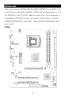
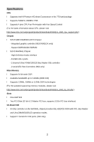
the package. 12. Press down the load lever lightly onto the load plate, and then secure the lever with the hook under retention tab. 13. Align the holes on the mainboard with the cooler. Push down the cooler until its four clips get wedged into the holes of the mainboard. 14. Press the four hooks down to fasten the cooler. Then rotate the locking switch (refer to the correct direction marked on it) to lock the hooks. 15. Turn over the mainboard to confirm that the clip-ends are correctly inserted. Note: If you want to uninstall the CPU, align the 4 points (see Point 8 for details) again and push the clip to lift up the CPU. Memory The mainboard provides two 184-pin unbuffered DDR333/DDR400 DDR SDRAM, and supports the memory size up to 2GB. To operate properly, at least one DIMM module must be installed. (For the updated supporting memory modules, please visit http://www.msi.com.tw/program/products/mainboard/mbd/pro_mbd_trp_list.php ) Install at least one DIMM module on the slots. Memory modules can be installed on the slots in any order. You can install either single- or double-sided modules to meet your own needs. Installing DDR Modules 1. The DDR DIMM has only one notch on the center of module. The module will only fit in the right orientation. 2. Insert the DIMM memory module vertically into the DIMM slot. Then push it in until the golden finger on the memory module is deeply inserted in the socket. 3. The plastic clip at each side of the DIMM slot will automatically close. Vol t Notc h 6
-
 1
1 -
2
-
3
-
4
-
 5
5 -
 6
6 -
 7
7 -
 8
8 -
 9
9 -
 10
10 -
 11
11 -
 12
12 -
 13
13 -
 14
14 -
 15
15 -
16
-
17
-
18
-
19
-
20
-
21
-
22
-
23
-
24
-
25
-
26
-
27
-
28
-
29
-
30
-
31
-
32
-
33
-
34
-
35
-
36
-
37
-
38
-
39
-
40
-
41
-
42
-
43
-
44
-
45
-
46
-
47
-
48
-
49
-
50
-
51
-
52
-
53
-
54
-
55
-
56
-
57
-
58
-
59
-
60
-
61
-
62
-
63
-
64
-
65
-
66
-
67
-
68
-
69
-
70
-
71
-
72
-
73
-
74
-
75
-
76
-
77
-
78
-
79
-
80
-
81
-
82
-
83
-
84
-
85
-
86
-
87
-
88
-
89
-
90
-
91
 |
 |
