MSI 745 ULTRA User Guide
MSI 745 ULTRA - Motherboard - ATX Manual
 |
View all MSI 745 ULTRA manuals
Add to My Manuals
Save this manual to your list of manuals |
MSI 745 ULTRA manual content summary:
- MSI 745 ULTRA | User Guide - Page 1
MSI MICRO-STAR INTERNATIONAL 745 Ultra 745 Ultra-E MS-6561 (v1.X) ATX Mainboard Version 1.1 G52-MA00564 i - MSI 745 ULTRA | User Guide - Page 2
frequency energy and, if not installed and used in accordance with the instruction manual, may cause harmful interference to radio communications. Operation of this equipment AVANT DE RACCORDER AU RESEAU. Micro-Star International MS-6561 Tested to comply with FCC Standard For Home or Office Use ii - MSI 745 ULTRA | User Guide - Page 3
Edition Feb. 2002 Copyright Notice The material in this document is the intellectual property of MICRO-STAR INTERNATIONAL. We take every care in the preparation of this document, but no guarantee is given as to the correctness of its contents. Our products are under continual improvement and we - MSI 745 ULTRA | User Guide - Page 4
1. Read the safety instructions carefully. 2. Save this User’s Guide for possible use later. 3. Keep this Always unplug the power cord before inserting any add-on card or module. 9. All cautions and warnings on the equipment should be noted. 10. Never pour any liquid into the opening that could - MSI 745 ULTRA | User Guide - Page 5
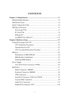
Specification 1-2 Mainboard Layout 1-4 Quick Components Guide 1-6 MSI Special Features 1-7 Fuzzy Logic™ III 1-7 PC Alert™ III 1-8 D-Bracket 1-9 Live BIOS™/Live Driver 1-11 Chapter 2. Hardware Setup 2-1 Central Processing Unit: CPU 2-2 CPU Installation Procedures 2-2 Thermal Issue for CPU - MSI 745 ULTRA | User Guide - Page 6
: JWR1 2-15 Front Panel Connectors: JFP1 & JFP2 2-16 Front Panel Audio Connector: JAUD1 2-17 Front USB Connector: JUSB1 2-18 Chassis Intrusion Switch 2-23 Clear CMOS Jumper: JBAT1 2-23 Slots 2-24 AGP (Accelerated Graphics Port) Slot 2-24 PCI Slots 2-24 CNR (Communication Network Riser 2-25 - MSI 745 ULTRA | User Guide - Page 7
Advanced BIOS Features 3-8 Advanced Chipset Features 3-12 Power Management Setup 3-14 PNP/PCI Configurations 3-18 Integrated Peripherals 3-21 PC Health Status 3-25 Frequency/Voltage Control 3-26 Load High Performance/BIOS Setup Defaults 3-28 Supervisor/User Password 3-29 Glossary ...G-1 vii - MSI 745 ULTRA | User Guide - Page 8
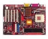
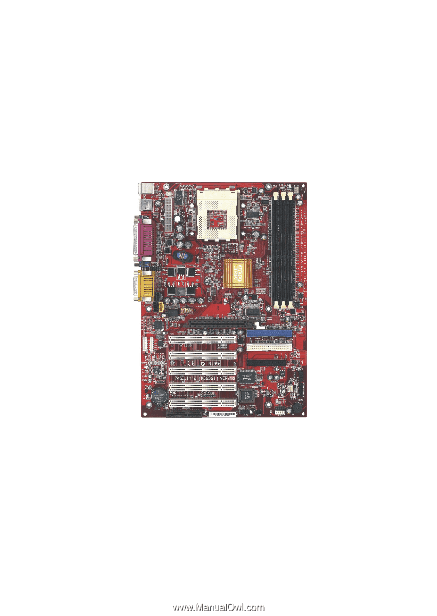
The MS6561 v1.X is based on SiS 745 chipset for optimal system efficiency. Designed to fit the advanced AMD® Athlon/Athlon XP/Duron processor in the Socket462 package, the MS-6561 delivers a high performance and professional desktop platform solution. TOPICS Mainboard Specification 1-2 Mainboard - MSI 745 ULTRA | User Guide - Page 9
Specification CPU Support Socket A (Socket-462) AMD® Athlon/Athlon XP/Duron processor up to 1900+MHz Support AMD PowerNow!TM technology Chipset Sis 745 Chipset - applies the multi-threaded architecture- “Build-in Multi-threaded I/O Link” to provide enough I/O bandwidth up to 1.2GB/s - supports - MSI 745 ULTRA | User Guide - Page 10
codec supports 2 channel Audio BIOS The mainboard BIOS provides “Plug & Play” function which detects the peripherals devices and expansion cards of the board automatically The mainboard provides a Desktop Management Interface (DMI) function which records your mainboard specifications Dimension ATX - MSI 745 ULTRA | User Guide - Page 11
Bottom: COM A COM B JDB1 Top : Game port Bottom: Line-Out Line-In Mic JMD1 JCD1 JAUX1 SiS 745 Codec B AT T + CNR PCI Slot 1 PCI Slot 2 PCI Slot 3 PCI Slot 4 JWR1 PCI Slot 5 IDE 1 IDE 2 FDD 1 BIOS JCI1 JBAT1 SFAN1 JFP1 JFP2 JAUD1 JIR1 JUSB1 745 Ultra (MS-6561 v1.X) ATX Mainboard 1-4 - MSI 745 ULTRA | User Guide - Page 12
port Bottom: Line-Out Line-In Mic JMD1 JCD1 JAUX1 SiS 745 DIM 1 DIM 2 DIM 3 J1394-2 J1394-1 Codec B AT T + CNR PCI Slot 1 PCI Slot 2 PCI Slot 3 PCI Slot 4 JWR1 PCI Slot 5 IDE 1 IDE 2 FDD 1 BIOS JCI1 JBAT1 SFAN1 JFP1 JFP2 JAUD1 JIR1 JUSB1 745 Ultra-E (MS-6561 v1.X) ATX Mainboard 1-5 - MSI 745 ULTRA | User Guide - Page 13
Quick Components Guide Component JPWR1 connector Front panel connectors Front panel audio connector Front USB connector Chassis Intrusion connector AGP card Connecting to expansion cards Connecting to expansion card Reference See p. 2-6 See p. 2-7 See p. 2-8 See p. 2-8 See p. 2-9 See p. 2-10 See - MSI 745 ULTRA | User Guide - Page 14
MSI Special Features Getting Started Fuzzy Logic™ III The Fuzzy Logic™ III utility allows users to overclock the CPU FSB (Front Side Bus) frequency in the Windows environment. Select the CPU frequency you prefer and click Go to apply the frequency or click Save allowing the system to run at the - MSI 745 ULTRA | User Guide - Page 15
CD-ROM disk. The utility is just like your PC doctor that can detect the following PC hardware status during real time operation: * monitor CPU & system temperatures * monitor fan speed(s) * monitor system voltage * monitor chassis intrusion If one of the items above is abnormal, the program main - MSI 745 ULTRA | User Guide - Page 16
below. The D-Bracket™ uses graphic signal display to help users problems or failures. 1 2 Red Green 3 4 Diagnostic LED D-Bracket Description 1 2 Processor Initialization - This will show information regarding the processor 3 4 (like brand name, system bus, etc...) Early Chipset - MSI 745 ULTRA | User Guide - Page 17
- This will start detecting CPU clock, checking type of video onboard. Then, detect and initialize the video adapter. BIOS Sign On -This will start showing information about logo, processor brand name, etc... Testing - This will set low stack and boot via INT 19h. Operating System Booting 1-10 - MSI 745 ULTRA | User Guide - Page 18
” message appears. l Live VGA Driver – Updates the VGA driver online. If your VGA device does not support the function, the “sorry” message is displayed. For more information on the update instructions, insert the companion CD and refer to the “Live Update Series Guide” under the “Manual” tab. 1-11 - MSI 745 ULTRA | User Guide - Page 19
, the components will not work properly. Use a grounded wrist strap before handling computer components. Static electricity may damage the components. TOPICS Central Processing Unit: CPU 2-2 Memory 2-4 Power Supply 2-6 Back Panel 2-7 Connectors 2-11 Jumpers 2-23 Slots 2-24 2-1 - MSI 745 ULTRA | User Guide - Page 20
CPU The mainboard supports AMD® Athlon/Athlon XP/Duron processor. The mainboard uses a CPU socket called Socket-462 for easy CPU installation. When you are installing the CPU, make sure the CPU install them before turning on the computer. CPU Installation Procedures 1. Pull the lever sideways away - MSI 745 ULTRA | User Guide - Page 21
thermal requirements. AMD recommends the use of high performance thermal interface material. AMD Athlon™ processor with a speed of 600MHz and above requires LARGER heatsink and fan. You also need to add thermal grease between the CPU and heatsink to improve heat dissipation. Then, make sure that the - MSI 745 ULTRA | User Guide - Page 22
Chapter 2 Memory The mainboard provides 3 slots for 184-pin, 2.5V unbuffered DDR DIMM. You can install PC1600/PC2100/PC2700 DDR SDRAM modules on the DDR DIMM slots (DDR 1~3). To operate properly, at least one DIMM module must be installed. DDR DIMM Slots (DDR 1~3) Introduction to DDR SDRAM DDR ( - MSI 745 ULTRA | User Guide - Page 23
Momory Module Slot 1 64MB, 128MB, 256MB, 512MB, 1GB Slot 2 64MB, 128MB, 256MB, 512MB, 1GB Slot 3 64MB, 128MB, 256MB, 512MB, 1GB Maximum System Memory Supported Total Memory 64MB~1GB 64MB~1GB 64MB~1GB 64MB~3GB Installing DDR Modules 1. The DDR DIMM has only one notch on the center of - MSI 745 ULTRA | User Guide - Page 24
down the power supply firmly into the connector. The power connector supports instant power on function which means that system will boot up 11 1 20 10 JPWR1 JPWR1 Pin Definition PIN SIGNAL 1 3.3V 2 3.3V 3 GND 4 5V 5 GND 6 5V 7 GND 8 PW_OK 9 5V_SB 10 12V PIN SIGNAL - MSI 745 ULTRA | User Guide - Page 25
Hardware Setup Back Panel The Back Panel provides the following connectors: Mouse Parallel Midi/Joystick Keyboard USB COM A COM B L-out L-in MIC Mouse Connector: JKBMS1 The mainboard provides a standard PS/2® mouse mini DIN connector for attaching a PS/2® mouse. You can plug a PS/2® mouse - MSI 745 ULTRA | User Guide - Page 26
Chapter 2 Keyboard Connector: JKBMS1 The mainboard provides a standard PS/2® keyboard mini DIN connector for attaching a PS/2® keyboard. You can plug a PS/2® keyboard directly into this connector. 6 5 4 3 2 1 PS/2 Keyboard (6-pin Female) Pin Definition PIN SIGNAL DESCRIPTION 1 Keyboard - MSI 745 ULTRA | User Guide - Page 27
) Ground Data Set Ready Request To Send Clear To Send Ring Indicate Joystick/Midi Connectors You can connect a joystick or game pad to this connector. Audio Port Connectors Line Out is a connector for Speakers or Headphones. Line In is used for external CD player, Tape player, or other - MSI 745 ULTRA | User Guide - Page 28
for LPT. A parallel port is a standard printer port that supports Enhanced Parallel Port (EPP) and Extended Capabilities Parallel Port (ECP) Data3 6 DATA4 Data4 7 DATA5 Data5 8 DATA6 Data6 9 DATA7 Data7 10 ACK# Acknowledge 11 BUSY Busy 12 PE Paper End 13 SELECT Select - MSI 745 ULTRA | User Guide - Page 29
IR module and CPU/System FAN. Floppy Disk Drive Connector: FDD1 The mainboard provides a standard floppy disk drive connector that supports 360K, 720K the setting through the BIOS setup to use the IR function. The JIR1 is compliant to Intel Front Panel I/O Connectivity Design Guide. 2-11 51 JIR1 - MSI 745 ULTRA | User Guide - Page 30
mode 0~4, Bus Master, and Ultra DMA/33/66/100 function. You can connect up to four hard disk drives, CD-ROM, 120MB Floppy (reserved for future BIOS) and other devices. These connectors support the provided IDE hard disk supplied by hard disk vendors for jumper setting instructions. 2-12 - MSI 745 ULTRA | User Guide - Page 31
Setup CD-In Connector: JCD1 The connector is for CD-ROM audio connector. Aux Line-In Connector: JAUX1 The connector is for DVD add-on card with Line-in connector. Modem-In Connector: JMD1 The connector is for modem with internal audio connector. JMD1 Mono_Out GND Phone_In JCD1 R GND L JAUX1 R GND - MSI 745 ULTRA | User Guide - Page 32
has a System Hardware Monitor chipset on-board, you must use a specially designed fan with speed sensor to take advantage of the CPU fan control. GND +12V SENSOR CFAN1 GND +12V SENSOR SFAN1 Note: 1. Always consult the vendor for proper CPU cooling fan. 2. CPU Fan supports the fan control. You can - MSI 745 ULTRA | User Guide - Page 33
Hardware Setup Wake On Ring Connector: JWR1 This connector allows you to connect to a modem card with Wake On Ring function. The connector will power up the system when a signal is received through the modem card. 1 5 JWR1 Pin Signal 1 NC 2 GND 3 MDM_WAKEUP 4 NC 5 5VSB 2-15 - MSI 745 ULTRA | User Guide - Page 34
electrical connection to the front panel switches and LEDs. Both JFP1 and JFP2 are compliant with Intel® Front Panel I/O Connectivity Design Guide. 10 9 _ PWSW + + _ RST S LED P _ HDD + 21 JFP1 SPK BUZ 87 + - P LED + S - GND 21 JFP2 JFP2 Pin Definition Pin Signal 1 GND 2 SPK - MSI 745 ULTRA | User Guide - Page 35
JAUD1 is compliant to Intel® Front Panel I/O Connectivity Design Guide. 9 1 10 2 JAUD1 Pin Definition PIN SIGNAL DESCRIPTION 1 AUD_MIC Front panel microphone input signal 2 AUD_GND Ground used by analog audio circuits 3 AUD_MIC_BIAS Microphone power 4 AUD_VCC Filtered +5V used - MSI 745 ULTRA | User Guide - Page 36
Serial Bus) pin header for users to connect to USB ports. JUSB1 is compliant with Intel® Front Panel I/O Connectivity Design Guide. 2 10 1 9 JUSB1 JUSB1 Pin Definition Pin Description Pin Description 1 USBPWR 2 USBPWR 3 USBP0- 4 USBP1- 5 USBP0+ 6 USBP1+ 7 GND 8 GND 9 NC - MSI 745 ULTRA | User Guide - Page 37
record this status and show a warning message on the screen. To clear the warning, you must enter the BIOS utility and clear the record. JCI1 is compliant with Intel® Front Panel I/O Connectivity Design Guide. 1 JCI1 JCI1 Pin Definition Pin Signal 1 CINTRU (Chassis intrusion) 2 GND 2-19 - MSI 745 ULTRA | User Guide - Page 38
Chapter 2 IEEE 1394 Connectors: J1394-1 & J1394-2 (optional) The mainboard provides two 1394 pin headers that allow you to connect optional IEEE 1394 ports. 1 1 J1394-2 J1394-1 Pin Signal 1 PWR 2 GND 3 TPB4 TPB+ Pin Signal 5 TPA6 TPA+ 7 SHLD 8 SHLD 2-20 - MSI 745 ULTRA | User Guide - Page 39
How to attach the IEEE 1394 Port: 1. Take out the IEEE 1394 Port. Hardware Setup 2. Locate the IEEE 1394 connectors (J6 & J7) on the mainboard. 3. Insert the IEEE 1394 Port into the connector. 4. Place the IEEE 1394 Port into the first slot of your system case. 2-21 - MSI 745 ULTRA | User Guide - Page 40
The mainboard comes with a JDB1 connector for you to connect to DBracket™. D-Bracket™ is a USB Bracket integrating four LEDs and allows users to identify system problem through 16 various combinations of LED signals. For definitions of 16 signal combinations, please refer to Chapter 1. DBracket - MSI 745 ULTRA | User Guide - Page 41
’s function. This section will explain how to change your motherboard’s function through the use of the jumper. Clear CMOS clear the system configuration, use the JBAT1 (Clear CMOS Jumper ) to clear data. Follow the instructions below to clear the data: 1 JBAT1 1 3 Keep CMOS 1 3 Clear CMOS You - MSI 745 ULTRA | User Guide - Page 42
Chapter 2 Slots The motherboard provides five 32-bit Master PCI bus slots, one AGP slot and one CNR slot. AGP Slot PCI Slots CNR Slot AGP (Accelerated Graphics Port) Slot The AGP slot allows you to insert the AGP graphics card. AGP is an interface specification designed for the throughput demands of - MSI 745 ULTRA | User Guide - Page 43
) The CNR slot allows you to insert the CNR expansion cards. CNR is a specially designed network, audio, or modem riser card for ATX family motherboards. Its main processing is done through software and controlled by the motherboard’s chipset. PCI Interrupt Request Routing The IRQ, abbreviation of - MSI 745 ULTRA | User Guide - Page 44
the default settings for customized features. TOPICS Entering Setup 3-2 The Main Menu 3-4 Standard CMOS Features 3-6 Advanced BIOS Features 3-8 Advanced Chipset Features 3-12 Power Management Setup 3-14 PNP/PCI Configurations 3-18 Integrated Peripherals 3-21 PC Health Status 3-25 - MSI 745 ULTRA | User Guide - Page 45
simultaneously pressing , , and keys. Selecting the First Boot Device You are allowed to select the 1st boot device without entering the BIOS setup utility by pressing . When the same message as listed above appears on the screen, press to trigger the boot menu. The - MSI 745 ULTRA | User Guide - Page 46
Decrease the numeric value or make changes Restore the previous CMOS value from CMOS, only for Option Page Setup Menu Load High Performance Defaults Load BIOS Setup Defaults Save all the CMOS changes and exit Getting Help After entering the Setup utility, the first screen you see is the Main Menu - MSI 745 ULTRA | User Guide - Page 47
for basic system configurations, such as time, date etc. Advanced BIOS Features Use this menu to setup the items of AMI® special enhanced features. Advanced Chipset Features Use this menu to change the values in the chipset registers and optimize your system’s performance. Power Management Setup Use - MSI 745 ULTRA | User Guide - Page 48
values for the best system performance, but the system stability may be affected. Load BIOS Setup Defaults Use this menu to load factory default settings into the BIOS for stable system performance operations. Save & Exit Setup Save changes to CMOS and exit setup. Exit Without Saving Abandon all - MSI 745 ULTRA | User Guide - Page 49
that you want (usually the current date). The format is . day Day of the week, from Sun to Sat, determined by BIOS. Read-only. month The month from Jan. through Dec. date The date from 1 to 31 can be keyed by numeric function keys. year The year - MSI 745 ULTRA | User Guide - Page 50
AMI BIOS Setup Pri Master/Pri Slave/Sec Master/Sec Slave Press PgUp/ or PgDn/ to select the hard disk drive type. The specification of for IDE Hard Disk boot sector protection. When Enabled, BIOS will issue a virus warning message and beep if a write to the boot sector or the partition table - MSI 745 ULTRA | User Guide - Page 51
Chapter 3 Advanced BIOS Features Quick Boot Setting the item to Enabled allows the system to boot within 5 seconds since it will skip some check items. Available options: Enabled - MSI 745 ULTRA | User Guide - Page 52
The system will boot from the first BBS (BIOS Boot Specification) compliant device. BBS-1 The system will boot from the second BBS (BIOS Boot Specification) compliant device. BBS-2 The system will boot from the third BBS (BIOS Boot Specification) compliant device. BBS-3 The system will boot - MSI 745 ULTRA | User Guide - Page 53
Floppy Drive Seek This setting causes the BIOS to search for floppy disk drives at boot time. When enabled, the BIOS will activate the floppy disk drives during the conventional DRAM (system memory). When the CPU requests data, the system transfers the requested data from the main DRAM into - MSI 745 ULTRA | User Guide - Page 54
Settings: Enabled and Disabled. MPS Table Version This field allows you to select which MPS (Multi-Processor Specification) version to be used for the operating system. You need to select the MPS version supported by your operating system. To find out which version to use, consult the vendor of your - MSI 745 ULTRA | User Guide - Page 55
chipset. DRAM Timing Configuration The DRAM timing is controlled by the DRAM Timing Registers. The Timings programmed into this register are dependent on the system design. Slower rates may be required in certain system designs to support to be determined by BIOS based on the configurations on - MSI 745 ULTRA | User Guide - Page 56
PCI memory address range dedicated for graphics memory address space. Host cycles that hit the aperture range are forwarded to the AGP without any translation. Settings: 4MB, 8MB, 16MB, 32MB, 64MB, 128MB. AGP Mode The item sets an appropriate mode for the installed AGP card. Settings are: 1x, 2x, 4x - MSI 745 ULTRA | User Guide - Page 57
saving modes for ACPI function. Options are: S1/POS The S1 sleep mode is a low power state. In this state, no system context is lost (CPU or chipset) and hardware maintains all system context. S3/STR The S3 sleep mode is a lower power state where the information of system cofiguration and open - MSI 745 ULTRA | User Guide - Page 58
and stop CPU internal clock. Settings are Disabled and Enabled. Init VGA BIOS By S3 This setting allows the system to initialize the VGA BIOS when period of system inactivity, all devices except the CPU shut off. Settings: Disabled, 1 min, 2 min, 3 min, 4 min, 5 min, 10 min, 15 min, 20 min, 30 min - MSI 745 ULTRA | User Guide - Page 59
from power savingh modes when activity or input signal of the specified hardware peripheral or component is detected. Note 1: You need to install a modem supporting power on function for Wake Up On Ring function. Note 2: If you change these settings, you must reboot the system until it enters the - MSI 745 ULTRA | User Guide - Page 60
AMI BIOS Setup The item specify how the system will be awakened from power saving mode when input signal of the keyboard is detected. If set to Specific Key, is the only one Power On event. If set to Password, please press to input password and its maximum password - MSI 745 ULTRA | User Guide - Page 61
which allows I/O devices to operate at speeds nearing the speed the CPU itself uses when communicating with its special components. This section covers O/S When set to YES, BIOS will only initialize the PnP cards used for booting (VGA, IDE, SCSI). The rest of the cards will be initialized by the PnP - MSI 745 ULTRA | User Guide - Page 62
Slot 1/5 IRQ, PCI Slot 2 IRQ, PCI Slot 3 IRQ, PCI Slot 4 IRQ This item specifies the IRQ line for each PCI slot. Settings: 3, 4, 5, 7, 9, 10, 11 and Auto. Selecting Auto allows BIOS to automatically determine the IRQ line for each PCI slot. Set IRQs to PCI or ISA Press to enter the sub - MSI 745 ULTRA | User Guide - Page 63
Access) channel is used. The settings determine if AMIBIOS should remove a DMA from the available DMAs passed to devices that are configurable by the system BIOS. The available DMA pool is determined by reading the ESCD NVRAM. If more DMAs must be removed from the pool, the end user can reserve - MSI 745 ULTRA | User Guide - Page 64
support or have any USB driver installed, such as DOS and SCO Unix. Setting options: Disabled, KeyB+Mouse+FDD. Audio Device Enabled allows the mainboard to detect whether an audio controller if you want to use other controller cards to connect an audio device. Settings: Enabled, Disabled. Modem - MSI 745 ULTRA | User Guide - Page 65
following screen appears: FDC Function This is used to enable or disable the onboard Floppy controller. Option Auto Enabled Disabled Description BIOS will automatically determine whether to enable the onboard Floppy controller or not. Enables the onboard Floppy controller. Disables the onboard - MSI 745 ULTRA | User Guide - Page 66
set to the ECP mode. When Parallel Port is set to Auto, the field will show Auto indicating that BIOS automatically determines the DMA channel for the parallel port. Available options: 0, 1, 3, Auto. OnBoard Midi Port is used to select the IRQ line for onboard Midi port. Options: 5, 10, 11. 3-23 - MSI 745 ULTRA | User Guide - Page 67
Chapter 3 OnBoard Game Port This item is used to specify the address for the onboard game port. The settings are: Disabled, 200h, and 208h. 3-24 - MSI 745 ULTRA | User Guide - Page 68
AMI BIOS Setup PC Health Status This section shows the status of your CPU, fan, warning for overall system status. message it will go back to Enabled. CPU Fan Detect Select Enabled to detect the CPU FAN status. If the CPU FAN stops runnoing, the system will beep and shows a warning message on the - MSI 745 ULTRA | User Guide - Page 69
CPU/system temperatures, CPU/System Fan speeds, Vcore etc. Monitor function is available only if there is hardware monitoring mechanism onboard. Spread Spectrum When the motherboard boost in clockspeed which may just cause your overclocked processor to lock up. Unused PCI Slot/DIMM Clock This - MSI 745 ULTRA | User Guide - Page 70
This setting controls the multiplier that is used to determine the internal clock speed of the processor relative to the external or motherboard clock speed. CPU Vcore Adjust This setting allows you to adjust the CPU core voltage. The default setting is Auto. Please note that it may be dangerous to - MSI 745 ULTRA | User Guide - Page 71
for the best system performance but probably will cause a stability issue. The BIOS Setup Defaults are the default values also set by the mainboard manufacturer for stable please CLEAR CMOS DATA to resolve the problem. For more information, refer to “Clear CMOS Jumper:JBAT1” in Chapter 2. 3-28 - MSI 745 ULTRA | User Guide - Page 72
AMI BIOS Setup Supervisor/User Password When you select Supervisor Password, a message as below will appear on the screen: When you select User Password, a message as below - MSI 745 ULTRA | User Guide - Page 73
Chapter 3 thorized use of your computer. The setting to determine when the password prompt is required is the PASSWORD CHECK option of the ADVANCED BIOS FEATURES menu. If the PASSWORD CHECK option is set to Always, the password is required both at boot and at entry to Setup. If set - MSI 745 ULTRA | User Guide - Page 74
power management specification enables the OS (operating system) to control the amount of power given to each device attached to the computer. Windows 98/98SE, Windows 2000 and Windows ME can fully support ACPI to allow users managing the system power flexibly. AGP (Accelerated Graphics Port) A new - MSI 745 ULTRA | User Guide - Page 75
small amount of battery-powered CMOS memory to retain the date, time, and system setup parameters. COM In MS-DOS system, the name of a serial communications port. DOS supports type and specification used in computer becomes variety, such as SDRAM, DDR SDRAM, and RDRAM. For further instruction, please - MSI 745 ULTRA | User Guide - Page 76
code card. The IDE interface is known as the ATA (AT Attachment) specification. IEEE 1394 A new, high speed external bus standard, also known as FireWire or iLink, which supports as disk drivers. LPT (line printer terminal) Logical device name for a line printer; a name reserved by the MS-DOS for - MSI 745 ULTRA | User Guide - Page 77
set of specifications that allows a PC to configure itself automatically to work with peripherals. The user can "plug" in a peripheral device and "play" it without configuring the system manually. To implement this useful feature, both the BIOS that supports PnP and a PnP expansion card are required
-
 1
1 -
 2
2 -
 3
3 -
 4
4 -
 5
5 -
 6
6 -
 7
7 -
8
-
9
-
10
-
11
-
12
-
13
-
14
-
15
-
16
-
17
-
18
-
19
-
20
-
21
-
22
-
23
-
24
-
25
-
26
-
27
-
28
-
29
-
30
-
31
-
32
-
33
-
34
-
35
-
36
-
37
-
38
-
39
-
40
-
41
-
42
-
43
-
44
-
45
-
46
-
47
-
48
-
49
-
50
-
51
-
52
-
53
-
54
-
55
-
56
-
57
-
58
-
59
-
60
-
61
-
62
-
63
-
64
-
65
-
66
-
67
-
68
-
69
-
70
-
71
-
72
-
73
-
74
-
75
-
76
-
77
 |
 |
i
Version 1.1
G52-MA00564
MS-6561 (v1.X) ATX Mainboard
MSI
MICRO-STAR INTERNATIONAL
745 Ultra
745 Ultra-E