MSI 915GM-FR User Manual
MSI 915GM-FR - Motherboard - Micro ATX Manual
 |
UPC - 816909006445
View all MSI 915GM-FR manuals
Add to My Manuals
Save this manual to your list of manuals |
MSI 915GM-FR manual content summary:
- MSI 915GM-FR | User Manual - Page 1
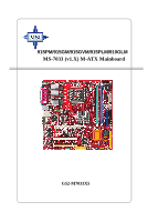
915PM/915GM/915GVM/915PLM/910GLM MS-7033 (v1.X) M-ATX Mainboard G52-M7033X5 i - MSI 915GM-FR | User Manual - Page 2
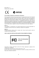
if not installed and used in accordance with the instruction manual, may cause harmful interference to radio communications. Operation the emission limits. VOIR LA NOTICE D'INSTALLATION AVANT DE RACCORDER AU RESEAU. Micro-Star International MS-7033 This device complies with Part 15 of the FCC Rules - MSI 915GM-FR | User Manual - Page 3
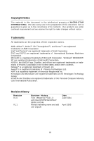
. Trademarks All trademarks are the properties of their respective owners. AMD, Athlon™, Athlon™ XP, Thoroughbred™, and Duron™ are registered trademarks of AMD Corporation. Intel® and Pentium® are 915P/915G/915GV/ 910GL & ICH6 Revise marketing name and add one chipset Date June 2004 April 2005 iii - MSI 915GM-FR | User Manual - Page 4
guide, BIOS updates, driver updates, and other information: http://www.msi.com.tw & http://www.msi. com.tw/program/service/faq/faq/esc_faq_list.php † Contact our technical staff at: [email protected] Safety Instructions 1. Always read the safety instructions carefully. 2. Keep this User's Manual 10 - MSI 915GM-FR | User Manual - Page 5
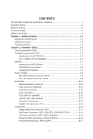
Pin Power Connector: ATX1 2-9 ATX 12V Power Connector: JPW 1 2-9 Back Panel ...2-10 Mouse/Keyboard Connector 2-10 VGA Connector (optional 2-10 Serial Port Connector 2-11 USB Connectors 2-11 IEEE1394 Port (optional 2-11 LAN (RJ-45) Jack (optional 2-12 Audio Port Connectors 2-12 Parallel Port - MSI 915GM-FR | User Manual - Page 6
Connector: JCD1 2-18 Front Panel Audio Connector: JAUD1 2-18 Serial Port Connector: JCOM2 2-19 Front USB Connectors: JUSB1 & JUSB2 2-19 SPDIF Connector: JSPD1 2-20 IEEE 1394 Connectors: JFW1 (optional 2-21 Jumpers ...2-21 Clear CMOS Jumper: JBAT1 2-21 Slots ...2-22 PCI Express Slots 2-22 PCI - MSI 915GM-FR | User Manual - Page 7
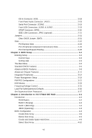
of Hard Drive 4-10 Duplicate Critical RAID 1 Array 4-11 Rebuild Broken RAID 0/0+1 Array 4-12 Installing Software 4-14 Install Driver in W indows XP/2000 4-14 Installation of VIA IDE RAID Utility 4-15 Using VIA RAID Tool 4-18 Chapter 5. Introduction to CMI 9880L Audio Codec 5-1 Installing the - MSI 915GM-FR | User Manual - Page 8
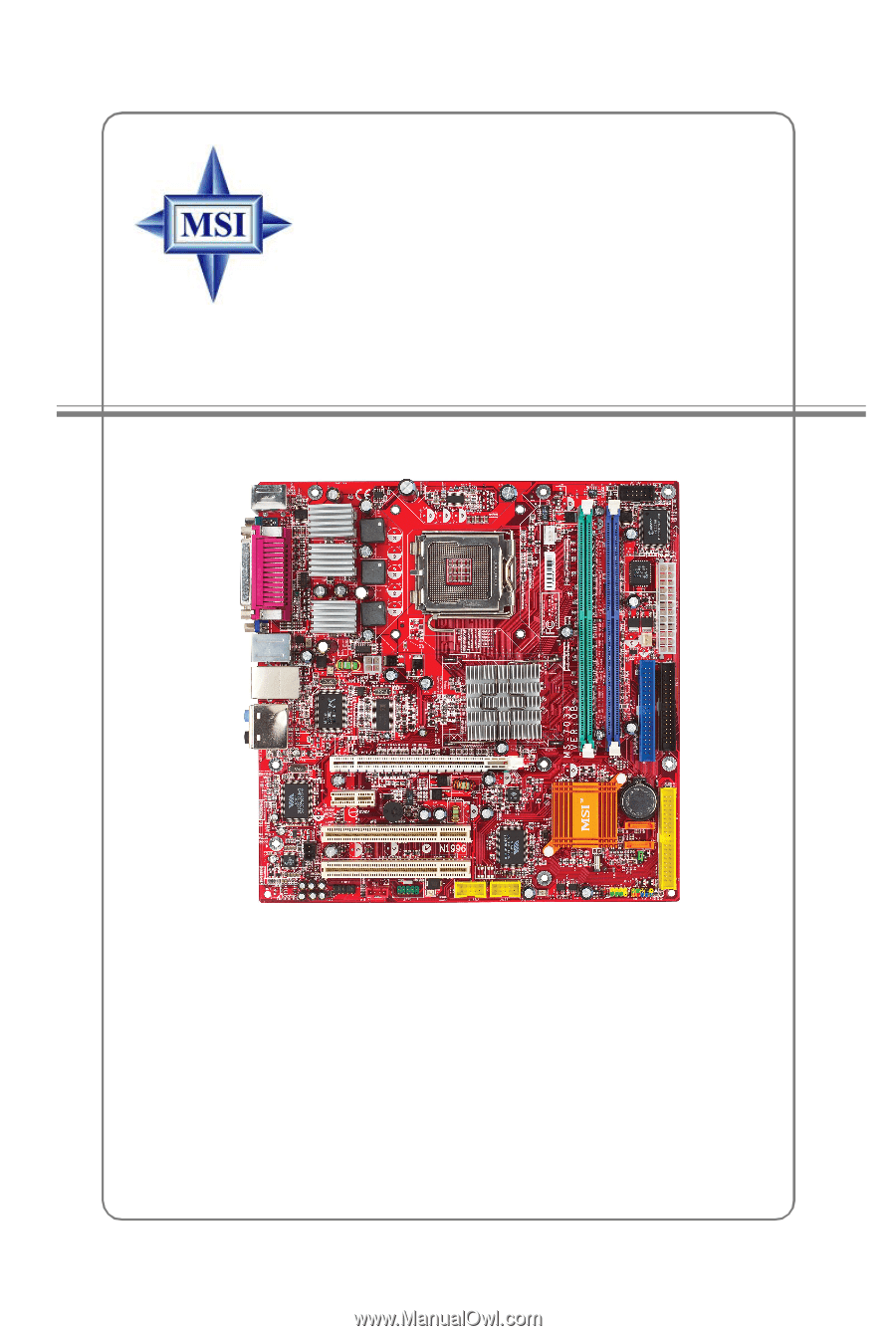
Getting Started Getting Started Thank you for choosing the 915PM/915PLM/915GM/ 915GVM/910GLM (MS-7033) v1.X M-ATX mainboard. The 915PM/ 915PLM /915GM/915GVM/910GLM mainboard is based on Intel® 915P/PL/G/GV/GL and Intel® ICH6 chipset for optimal system efficiency. Designed to fit the advanced Intel - MSI 915GM-FR | User Manual - Page 9
information about CPU, please visit http://www.msi.com.tw/program/ products/mainboard/mbd/pro_mbd_cpu_support.php) Chipset † Intel® 915P/915PL/915G/915GV/910GL Chipset - Supports 533/800MHz Intel NetBurst micro-architecture bus (910GL supports 533 MHz only) - Supports PCI Express x16 interface - MSI 915GM-FR | User Manual - Page 10
via pin header(IO bracket is optional) - 1 parallel port supports SPP/EPP/ECP mode - 1 Line-In / Line-Out / MIC-In / Surround Speaker Out / Center-Subwoofer Speaker Out / Surround Back Speaker Out - 8 USB ports (Rear * 4/ Front * 4) - 1 RJ-45 LAN jack (optional) - 2 * 1394 ports (optional) On-board - MSI 915GM-FR | User Manual - Page 11
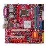
M S-7033 M -ATX M ainboard Mainboard Layout Top : mouse Bottom: keyboard Top : Parallel Port Bottom: COM port VGA port (optional) CPU_FAN1 CPU_FAN2 Winbond W83627THF JCOM2 AT X1 B IOS T:IEEE 1394 (optional) B:USB port JP W1 T: LAN jack (optional) B: USB ports T:Line-In M:Line-Out B:Mic - MSI 915GM-FR | User Manual - Page 12
Packing Contents Getting Started MSI motherboard MSI Driver/Utility CD Back IO Shield User's Guide 1-5 - MSI 915GM-FR | User Manual - Page 13
Chapter 2. Hardware Setup Hardware Setup This chapter tells you how to install the CPU, memory modules, and expansion cards, as well as how to setup the jumpers on the mainboard. Also, it provides the instructions on connecting the peripheral devices, such as the mouse, keyboard, etc. W hile doing - MSI 915GM-FR | User Manual - Page 14
M S-7033 M -ATX M ainboard Quick Components Guide JPW1, p.2-9 CPU, p.2-3 CPUF_FAN1 CPUF_FAN2, p.2-14 DDR DIMMs, p.2-7 JCOM2, p.2-19 Back Panel I/O, p.2-10 PCI Express x16, p.2-22 PCI Express x1, p.2-22 PCI Slots 2/3, p.2-22 JSPD1, p.2-20 JAUD1, p.2-18 JCD1, p.2-18 JFW1, p.2-20 (Optional) - MSI 915GM-FR | User Manual - Page 15
to protect the CPU from overheating. Replacing the CPU While replacing the CPU, always turn off the ATX power supply or unplug the power supply's power cord from grounded outlet first to ensure the safety of CPU. Overclocking This motherboard is designed to support overclocking. However, please - MSI 915GM-FR | User Manual - Page 16
M S-7033 M -ATX M ainboard CPU, Heatsink & Fan Installation W hen you are installing the CPU, make sure the CPU has a heat sink/ cooler fan attached on the top to prevent overheating. If you do not have the heat sink/cooler fan, contact your dealer - MSI 915GM-FR | User Manual - Page 17
. Be sure to grape on the edge of the substrate. Note that the alignment keys are matched. alignment key 7. Visually inspect if the CPU is seated well into the socket. If not, take out the CPU with purely vertical motion and reload it again. 8. Rotate the load plate onto the p ac kage. 2-5 - MSI 915GM-FR | User Manual - Page 18
-ATX M ainboard 9. Engage the load while pressing down lightly onto the load plate, and then secure the lever with the hook under retention tab. 10 the clip-ends are corrected inserted. locking switch MSI Reminds You... 1. Confirm if your CPU heatsink/cooler is firmly installed before turning on - MSI 915GM-FR | User Manual - Page 19
memory size up to 2GB. You can install DDR266/ 333/400 modules on the DDR DIMM slots (DDR 1~2). For the updated supporting memory modules, please visit http://www.msi.com.tw/ program/products/mainboard/mbd/pro_mbd_trp_list.php. DDR DIMM Slots (DDR 1~2) Introduction to DDR SDRAM DDR (Double Data Rate - MSI 915GM-FR | User Manual - Page 20
M -ATX M ainboard & 1) DDR 2 (Bank 2 & 3) Memory Module S/D S/D Maximum System Memory Supported S: Single Side D: Double Side Total Memory 64MB~1GB 64MB~1GB 64MB~2GB Installing slot will automatically close. Volt Notch MSI Reminds You... You can barely see the golden finger if the module - MSI 915GM-FR | User Manual - Page 21
Connector: JPW1 This 12V power connector is used to provide power to the CPU. 2 1 JPW1 4 3 JPW1 Pin Definition PIN SIGNAL 1 GND 2 GND 3 12V 4 12V MSI Reminds You... 1. These two connectors connect to the ATX power supply and have to work together to ensure stable operation of the - MSI 915GM-FR | User Manual - Page 22
ATX M ainboard Back Panel The back panel provides the following connectors: Mouse Parallel IEEE1394 LAN (Optional) L-In Surround (Optional) Center/ Subwoofer Keyboard COM port VGA port (Optional) USB 7 GND 8 GND 9 +5V 10 GND 11 N/C 12 SDA 13 Horizontal Sync 14 Vertical Sync 15 - MSI 915GM-FR | User Manual - Page 23
) The back panel provides one standard IEEE 1394 port. The standard IEEE 1394 port connects to IEEE 1394 devices without external power. The IEEE 1394 high-speed serial bus complements USB by providing enhanced PC connectivity for a wide range of devices, including consumer electronics audio/video - MSI 915GM-FR | User Manual - Page 24
M S-7033 M -ATX M ainboard LAN (RJ-45) Jack (optional) The mainboard provides 1 standard RJ-45 jack for connection to single Local Area Network (LAN). This Giga-bit LAN enables data to be transferred at 1000, 100 or 10Mbps. You can connect a network cable to it. RJ-45 LAN Jack Giga-bit LAN Pin - MSI 915GM-FR | User Manual - Page 25
connector as LPT. A parallel port is a standard printer port that supports Enhanced Parallel Port (EPP) and Extended Capabilities Parallel Port (ECP) 6 DATA4 Data4 7 DATA5 Data5 8 DATA6 Data6 9 DATA7 Data7 10 ACK# Acknowledge 11 BUSY Busy 12 PE PaperEnd 13 SELECT Select 14 - MSI 915GM-FR | User Manual - Page 26
M S-7033 M -ATX M ainboard Connectors The mainboard provides connectors to connect to FDD, IDE HDD, case, LAN, USB Ports, IR module and CPU/System FAN. Floppy Disk Drive Connector: FDD1 The mainboard provides a standard floppy disk drive connector that supports 360K, 720K, 1.2M, 1.44M and 2.88M - MSI 915GM-FR | User Manual - Page 27
. MSI Reminds You... If you install two hard disks on cable, you must configure the second drive to Slave mode by setting its jumper. Refer to the hard disk documentation supplied by hard disk vendors for jumper setting instructions. If you want to use RAID function, please make a RAID driver from - MSI 915GM-FR | User Manual - Page 28
-ATX M ainboard Serial ATA HDD Connectors: SATA1 & SATA2 The mainboard provides dual high-speed Serial ATA interface ports. The ports support 1st ports Take out the dust cover and connect to the hard disk d evi c es MSI Reminds You... Please do not fold the serial ATA cable in a 90-degree angle, - MSI 915GM-FR | User Manual - Page 29
& JFP2 The mainboard provides two front panel connectors for electrical connection to the front panel switches and LEDs. JFP1 is compliant with Intel® Front Panel I/O Connectivity Design Guide. Speaker JFP2 2 1 8 7 Power LED Power Power LED Switch 2 1 10 9 JFP1 HDD Reset LED Switch JFP1 - MSI 915GM-FR | User Manual - Page 30
panel audio and is compliant with Intel® Front Panel I/O Connectivity Design Guide. 2 1 10 9 JAUD1 JAUD2 Pin Definition PIN SIGNAL DESCRIPTION 1 PORT 1L Analog Port 1 - Left channel 2 GND Ground 3 PORT 1R Analog Port 1 - Right channel 4 PRESENCE# Active low signal - signals BIOS - MSI 915GM-FR | User Manual - Page 31
You can attach a serial mouse or other serial device directly to it. 2 10 1 9 JCOM2 Pin Definition PIN SIGNAL DESCRIPTION 1 DCD 2 SIN 3 SOUT Ring Indicate Front USB Connectors: JUSB1 & JUSB2 The mainboard provides two standard USB 2.0 pin headers JUSB1 & JUSB2 . USB 2.0 technology - MSI 915GM-FR | User Manual - Page 32
S-7033 M -ATX M ainboard SPDIF Connector: JSPD1 The connector is used to connect SPDIF (Sony & Philips Digital Interconnect Format) interface for digital audio transmission. 3 JSPD1 1 JSPD1 Pin Definition PIN SIGNAL 1 VCCS 2 SPDIF0 3 GND Connected to JSPD1 The JSPD1 supports SPDIF output - MSI 915GM-FR | User Manual - Page 33
computer's function. This section will explain how to change your motherboard's function through the use of jumpers. Clear CMOS Jumper: JBAT1 Jumper ) to clear data. Follow the instructions below to clear the data: 1 JBAT1 1 1 3 Keep Data 3 Clear Data MSI Reminds You... You can clear CMOS by - MSI 915GM-FR | User Manual - Page 34
designs with transfer rates of 4.0 GB/s over a PCI Express x16 lane for graphics controllers, while PCI Express x1 supports transfer rate of 250 MB/s. PCI Express x16 slot PCI Express x1 slot MSI Reminds You... 1. The PCI Express x16 slot also supports ADD2 interface card when it is presented on PCI - MSI 915GM-FR | User Manual - Page 35
documentation for the expansion card to make any necessary hardware or software settings for the expansion card, such as jumpers, switches or BIOS configuration. PCI Slots PCI Interrupt Request Routing The IRQ, acronym of interrupt request line and pronounced I-R-Q, are hardware lines over which - MSI 915GM-FR | User Manual - Page 36
you to run SETUP. ² You want to change the default settings for customized features. MSI Reminds You... 1. The items under each BIOS category described in this chapter are under continuous update for better system performance. Therefore, the description may be slightly different from the latest - MSI 915GM-FR | User Manual - Page 37
M S-7033 M -ATX M ainboard Entering Setup Power on the computer and the system will start POST (Power On Self Test) process. W hen the message below appears on the - MSI 915GM-FR | User Manual - Page 38
the possible selections for the highlighted item. Press to exit the Help s c r een . MSI Reminds You... The items under each BIOS category described in this chapter are under continuous update for better system performance. Therefore, the description may be slightly different from the latest - MSI 915GM-FR | User Manual - Page 39
ATX M ainboard The Main Menu Once you enter Award® BIOS BIOS Features Use this menu to setup the items of Award® special enhanced features. Advanced Chipset Features Use this menu to change the values in the chipset system supports PnP/PCI. H/W Monitor This entry shows information of your CPU, fan - MSI 915GM-FR | User Manual - Page 40
best system performance, but the system stability may be affected. Load Optimized Defaults Use this menu to load factory default settings into the BIOS for stable system performance operations. Set Supervisor Password Use this menu to set Supervisor Password. Set User Password Use this menu to set - MSI 915GM-FR | User Manual - Page 41
-ATX M day month date year Day of the week, from Sun to Sat, determined by BIOS. Read-only. The month from Jan. through Dec. The date from 1 to Primary/Secondary/Third/Fourth Master/Slave Press PgUp/ or PgDn/ to select [Manual], [None] or [Auto] type. Note that the specifications of your drive - MSI 915GM-FR | User Manual - Page 42
BIOS Setup If you select [Manual [2.88M, 3.5 in.] Video The setting controls the type of video adapter used for the BIOS Version This item shows the memory status and BIOS version of your system (read only). **CPU Information** CPU Type/CPU ID/uCode ID/CPU Frequency The four items show the CPU - MSI 915GM-FR | User Manual - Page 43
to execute the instructions. Settings: [Enabled], [Disabled]. MSI Reminds You... Enabling the functionality of Hyper-Threading Technology for your com- puter system requires ALL of the following platform Components: * CPU: An Intel® Pentium® 4 Processor with HT Technology; * Chipset: An Intel - MSI 915GM-FR | User Manual - Page 44
allows you to select which MPS (Multi-Processor Specification) version to be used for the operating system. You need to select the MPS version supported by your operating system. To find out which version to use, consult the vendor of your operating system. Setting options: [1.4], [1.1]. Boot to OS - MSI 915GM-FR | User Manual - Page 45
M S-7033 M -ATX M ainboard 1st/2nd/3rd Boot Device These items allow you to set the sequence of boot devices where AMIBIOS attempts to load the operating system. MSI Reminds You... Available settings for "1st/2nd/3rd Boot to boot from the 1st/2nd/3rd boot device. Settings are: [Yes], [No]. 3-10 - MSI 915GM-FR | User Manual - Page 46
chipset. DRAM Timing Selectable Selects whether DRAM timing is controlled by the SPD (Serial Presence Detect) EEPROM on the DRAM module. Setting to [Auto By SPD] enables DRAM timings and the following related items to be determined by BIOS based on the configurations on the SPD. Selecting [Manual - MSI 915GM-FR | User Manual - Page 47
-ATX M ainboard DRAM RAS# Precharge (tRP) W hen the DRAM Timing Control is set to [Manual], Video BIOS Cacheable Selecting [Enabled] allows caching of the video memory (RAM) at A0000h to AFFFFh, resulting in better video PCI Express Port Func Press and the following sub-menu appears: 3- - MSI 915GM-FR | User Manual - Page 48
BIOS Setup PCI Express Port You can set PCI Express port. Setting options: [Disabled], [Enabled], [Auto]. PCI-E PEG (PCI Express Graphic) port function. Setting options: [Enabled], [Disabled]. On-Chip Frame Buffer Size Frame Buffer is the video memory that stores data for video display (frame - MSI 915GM-FR | User Manual - Page 49
the operating system that does not support or does not have any USB driver installed, such as DOS and SCO Unix. Azalia/AC97 Audio [Auto] allows the mainboard to detect whether an audio device is used. If an audio device is detected, the onboard Azalia/AC97 (Audio Codec'97) controller will be enabled - MSI 915GM-FR | User Manual - Page 50
BIOS Setup Onboard LAN The item enables or disables the onboard LAN controller. Setting options: [Enabled], [Disabled]. OnBoard 1394 (optional) This setting is used to enable/disable the onboard IEEE 1394 controller. Setting options: [Enabled], [Disabled]. IO - MSI 915GM-FR | User Manual - Page 51
M S-7033 M -ATX M ainboard Onboard COM Port 1/COM Port 2 This item specifies the base I/O port address and IRQ for the onboard Serial Port 1 (LPT1B)/Serial Port 2 (JCOM1). Selecting [Auto] allows BIOS to automatically determine the correct base I/O port address. Setting options: [Disabled], [3F8/ - MSI 915GM-FR | User Manual - Page 52
menu appears: IDE HDD Block Mode Block mode is also called block transfer, multiple commands, or multiple sector read/write. If your IDE hard drive supports block mode (most new drives do), select [Enabled] for automatic detection of the optimal number of block read/ writes per sector the drive can - MSI 915GM-FR | User Manual - Page 53
M S-7033 M -ATX M ainboard IDE Primary Master/Slave Ultra DMA Ultra DMA 33/66/100/133 implementation is possible only if your IDE hard drive supports it and the operating environment includes a DMA driver (Windows ME, XP or a third-party IDE bus master driver). If your hard drive and your system - MSI 915GM-FR | User Manual - Page 54
Power Management Setup BIOS Setup ACPI Standby State This item specifies the power saving modes for ACPI function. Options are: [S1/POS] The S1 sleep mode is a low power state. In this state, no system context is lost (CPU or chipset) and hardware maintains all system context. [S3/STR] The - MSI 915GM-FR | User Manual - Page 55
M S-7033 M -ATX M ainboard Wake Up Event Setup Press and the following sub-menu appears: PCI Express PME You can enable/disable PCI Express PME function. Setting options: [Enabled], [Disabled]. Resume by PCI Device (PME#) This controls how and whether the system can be powered on by the - MSI 915GM-FR | User Manual - Page 56
items specify the IRQ line for each PCI slot. Setting options: [3], [4], [5], [7], [9], [10], [11], [12], [14], [15], [Auto]. Selecting [Auto] allows BIOS to automatically determine the IRQ line for each PCI slot. ** PCI Express relative items ** Maximum Payload size It allows you to set the maximum - MSI 915GM-FR | User Manual - Page 57
Warning Temperature This item is used to specify a thermal limit for CPU. If CPU temperature reaches the specified limit, the system will issue a warning and allows you to prevent the CPU overheating problem. Settings: [Disabled], [50°C/122°F], [53°C /127°F], [56°C /133°F], [60°C /140°F], [63°C /145 - MSI 915GM-FR | User Manual - Page 58
and the following sub-menu appears. BIOS Setup CPU/System Temperature, CPU/System/Power FAN Speed, Vcore, +5.0V, +12. 0V, VBAT (V), +5VSB These items display the current status of all of the monitored hardware devices/ components such as CPU voltages, temperatures and all fans' speeds - MSI 915GM-FR | User Manual - Page 59
-ATX M ainboard Frequency/Voltage Control Use this menu to specify your settings for frequency/voltage control. Current CPU Clock It shows the current clock frequency of CPU. (Read-only) Adjust CPU Ratio End users can overclock the processor (only if the processor supports so) by specifying the CPU - MSI 915GM-FR | User Manual - Page 60
BIOS Setup M emory Voltage Adjusting the DDR voltage can increase the DDR speed. Any changes made to this setting may cause a stability issue, so changing the DDR voltage for long-term purpose is NOT recommended. PCI Express Voltage PCI Express voltages are adjustable in the field, allowing you to - MSI 915GM-FR | User Manual - Page 61
S-7033 M -ATX M ainboard Load Fail-Safe/Optimized Defaults The two options on the main menu allow users to restore all of the BIOS settings to the of the mainboard. The Fail-Safe Defaults are the default values set by the BIOS vendor for stable system perf or manc e. W hen you select Load Fail-Safe - MSI 915GM-FR | User Manual - Page 62
when the password prompt is required in the Security Option of the Advanced BIOS Feature menu. If the Security Option is set to [System], the [Setup], password prompt only occurs when you try to enter Setup. MSI Reminds You... About Supervisor Password & User Password: Supervisor password: Can - MSI 915GM-FR | User Manual - Page 63
RAID software is a W indows-based software utility. Its graphical user interface provides an easy way to configure and manage disk Supports hot-swap failed disk drive in RAID 1. 13. Mirroring automatic background rebuilds support. 14. ATA SMART function support. 15. Event log for easy troubleshooting - MSI 915GM-FR | User Manual - Page 64
introduction on VIA IDE RAID Host Controller. For users wishing to install their VIA IDE RAID driver and RAID software, proceed to Installing Software s ec ti on . Note: RAID option supports only one IDE channel with RAID 0/1 configuration. RAID Basics RAID (Redundant Array of Independent Disks) is - MSI 915GM-FR | User Manual - Page 65
the next drive in the array. W hen any disk member fails, the failure affects the entire array. JBOD is not really a RAID and does not support fault tolerance. 4-3 - MSI 915GM-FR | User Manual - Page 66
ATX M ainboard BIOS Configuration W hen the system powers on during the POST (Power-On Self Test) process, press key to enter the BIOS configuration. The VIA IDE RAID volume may be configured using the VIA Tech. RAID BIOS of BIOS configuration utility is as below: MSI Reminds You... 1. The - MSI 915GM-FR | User Manual - Page 67
up and down arrow keys to select the Create Array command and press . 0 MSI Reminds You... The "Channel", "Drive Name", "Mode" and "Size (GB)" in select Create only or Create and duplicate. Create only will allow BIOS to only create an array. The data on the mirroring drive may be different - MSI 915GM-FR | User Manual - Page 68
M S-7033 M -ATX M ainboard After array mode is selected, there are two methods to create a disk array. One method is "Auto Setup" and the other one is "Select Disk Drives". Auto Setup allows BIOS to select the disk drives and create arrays automatically, but it does not duplicate the mirroring - MSI 915GM-FR | User Manual - Page 69
Introduction to VIA VT6410 IDE RAID MSI Reminds You... Even though 64KB is the recommended setting for most users, you should choose the block size value which is best suited to your - MSI 915GM-FR | User Manual - Page 70
M S-7033 M -ATX M ainboard Delete Disk Array A RAID can be deleted after it has been created. To delete a RAID, use the following steps: 1. Select Delete Array in the - MSI 915GM-FR | User Manual - Page 71
Introduction to VIA VT6410 IDE RAID Create and Delete Spare Hard Drive If a RAID 1 array is created and there are drives that do not belong to other arrays, the one that has a capacity which is equal to or greater than the array capacity can be selected as a spare drive for the RAID 1 array. Select - MSI 915GM-FR | User Manual - Page 72
M S-7033 M -ATX M ainboard Select Boot Array User can select a disk array as boot device if user wants to boot operating system from an array. Boot disk array F1 key to show the array status on the lower screen. If there are no disk arrays then nothing will be displayed on the screen. 0 4-10 - MSI 915GM-FR | User Manual - Page 73
will detect if the RAID 1 array has any inconsistencies between user data and backup data. If BIOS detects any inconsistencies, the status of the disk array will be marked as critical, and BIOS will prompt the user to duplicate the RAID 1 in order to ensure the backup data consistency with the user - MSI 915GM-FR | User Manual - Page 74
will provide several operations to solve such problem. 1. Power off and Check the Failed Drive: This item turns off the computer and replaces the failed hard drive with a good one. If your computer does not support APM, you must turn off your computer manually. After replacing the hard drive, boot - MSI 915GM-FR | User Manual - Page 75
rebuild, or press N to cancel. Please note selecting option Y will destroy all the data on the selected hard drive. 4. Continue to boot: This item enables BIOS to skip the problem and continue booting into OS. 4-13 - MSI 915GM-FR | User Manual - Page 76
the MSI CD into the CD-ROM drive. 2. The CD will auto-run and the setup screen will appear. 3. Under the Driver tab, click on VIA IDE RAID Drivers. 4. The drivers will be automatically installed. † Confirming Windows XP/2000 Driver Installation 1. From W indows XP/2000, open the Control Panel from - MSI 915GM-FR | User Manual - Page 77
is the software package that enables high-performance in the W indows XP/2000 operating system. This version of VIA IDE RAID Utility contains the following key features: † IDE RAID driver † VIA IDE RAID utility † RAID0, RAID1 & functions Insert the MSI CD and click on the VIA IDE RAID Utility to - MSI 915GM-FR | User Manual - Page 78
M S-7033 M -ATX M ainboard The InstallShield Wizard will begin automatically for installation. Click on the Next button to proceed the installation in the welcoming window. Select I Agree to accept the VIA Software License Agreement, and click on the Next button to continue. 4-16 - MSI 915GM-FR | User Manual - Page 79
Introduction to VIA VT6410 IDE RAID Put a check mark in the check box to install the feature you want. Then click Next button to proceed the installation. Remember to restart your computer before using this newly installed program. 4-17 - MSI 915GM-FR | User Manual - Page 80
M S-7033 M -ATX M ainboard Using VIA RAID Tool Once the installation is complete, go to Start on these toolbar buttons to execute their specific functions. The left window pane displays the controller and disk drives. The right window pane displays the details of the controller or disk drives. In - MSI 915GM-FR | User Manual - Page 81
pane. There are two viewing types: By controllers and by device. Click on the object in the left window pane to display the status of the object in the right window pane. The following screen shows the status of Array 0---RAID 0. Click on the plus (+) symbol next to Array 0---RAID 0 to see - MSI 915GM-FR | User Manual - Page 82
M S-7033 M -ATX M ainboard You may also use the same or 0---RAID 1. button to view the statuses of Array Click on the plus (+) symbol next to Array 0---RAID 1 to see the details of each disk. 4-20 - MSI 915GM-FR | User Manual - Page 83
Codec Introduction to CMI 9880L Audio Codec The motherboard comes with CMI9880L audio chip, which supports the brand new Azalia specification. In addition, C-Media designs a multi-stream function which allows the rear audio & front panel to play different audio sources simultaneously. CMI 9880L also - MSI 915GM-FR | User Manual - Page 84
M S-7033 M -ATX M ainboard Installing the Audio Codec Driver To install C-Media drivers: 1. Insert the MSI CD into the CD-ROM drive. The setup screen will automatically appear. 2. Click on C-M edia Azalia Audio Driver. 3. Follow the on-screen instructions to complete installation. 4. Restart the - MSI 915GM-FR | User Manual - Page 85
of the audio. Main Setting 1. Audio System Status This menu shows you the current audio system status of channel (for example: 7.1CH), S/PDIF out and S/PDIF in . The status will change as you change the settings in the following audio jack (it includes rear panel/front panel/digital IO - MSI 915GM-FR | User Manual - Page 86
ATX M ainboard 2. Audio Jack This part shows the audio jack on your mainboard and indicates each function. (1) Rear Panel The audio configuration shown here should be identical to the audio jacks on your mainboard. Follow the indication on it to connect the audio : "Line Input Audio Device" and " - MSI 915GM-FR | User Manual - Page 87
two options to choose: "Back Surround Speaker (Lb/Rb)" and "Unused/Undefined". The connector's function depends on your selection. (2) Front Panel For the front panel audio jack, usually the green one is connected to Line-Out device while the pink one is for MIC. ----G ----H G. Green connector - MSI 915GM-FR | User Manual - Page 88
M S-7033 M -ATX M ainboard 3. DSP M ode: Disabled This part provides an advanced, amazing and remains gray. Here you can test each connected speaker by clicking button to ensure if each channel audio operation works properly. If any speaker fails to make sound, then check whether the cable is - MSI 915GM-FR | User Manual - Page 89
to CMI9880L Audio Codec sound to human ears. Thus, please move it horizontally to express strength or weakness. Toolbar of DPS Mode -clockwise. Move all the virtual speakers clockwise/anti- clockwise manually. Move individual virtual speaker randomly. Reset the change - MSI 915GM-FR | User Manual - Page 90
M S-7033 M -ATX M ainboard Mixer 1. Multi-Stream Function CMI9880L supports an outstanding feature called Multi-Stream, which means you may play different audio sources simultaneously and let them output respectively from the indicated real panel or front panel. This feature is very helpful when 2 - MSI 915GM-FR | User Manual - Page 91
Introduction to CMI9880L Audio Codec In the Mixer part, you may adjust the volumes of the rear and front panels individually. (1) C-Media Rear Panel Audio photo: (2) C-Media Front Panel Audio photo: 5-9 - MSI 915GM-FR | User Manual - Page 92
M S-7033 M -ATX M ainboard 2. Recording If you want to use microphone to record, usually the microphone is connected to the MIC jack (the pink one) in the rear audio panel. You can start recording in this case. ----A Click button to play the voice you are recording, or click to stop it. 5-10 - MSI 915GM-FR | User Manual - Page 93
and you have to switch it to the C-Media Azalia Front Panel. Device Setting The settings here have the same functionality as the configurations of Sound playback & Sound recording in the Sounds and Audio Devices Properties dialogue in Control Panel. You can set the desired settings of Sound playback - MSI 915GM-FR | User Manual - Page 94
save them for the future usage. Information In this tab it provides some information about the Azalia Audio Configuration utility, including 3D Audio Engine, Audio Codec, Audio Driver Version, Audio Controller & DirectX Version. You may also select the language of this utility by choosing from the - MSI 915GM-FR | User Manual - Page 95
-
 1
1 -
 2
2 -
 3
3 -
 4
4 -
 5
5 -
 6
6 -
 7
7 -
8
-
9
-
10
-
11
-
12
-
13
-
14
-
15
-
16
-
17
-
18
-
19
-
20
-
21
-
22
-
23
-
24
-
25
-
26
-
27
-
28
-
29
-
30
-
31
-
32
-
33
-
34
-
35
-
36
-
37
-
38
-
39
-
40
-
41
-
42
-
43
-
44
-
45
-
46
-
47
-
48
-
49
-
50
-
51
-
52
-
53
-
54
-
55
-
56
-
57
-
58
-
59
-
60
-
61
-
62
-
63
-
64
-
65
-
66
-
67
-
68
-
69
-
70
-
71
-
72
-
73
-
74
-
75
-
76
-
77
-
78
-
79
-
80
-
81
-
82
-
83
-
84
-
85
-
86
-
87
-
88
-
89
-
90
-
91
-
92
-
93
-
94
-
95
 |
 |
G52-M7033X5
MS-7033 (v1.X) M-ATX Mainboard
915PM/915GM/915GVM/915PLM/910GLM