MSI 915GM-FR User Manual - Page 26
Connectors - chipset
 |
UPC - 816909006445
View all MSI 915GM-FR manuals
Add to My Manuals
Save this manual to your list of manuals |
Page 26 highlights
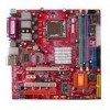
M S-7033 M -ATX M ainboard Connectors The mainboard provides connectors to connect to FDD, IDE HDD, case, LAN, USB Ports, IR module and CPU/System FAN. Floppy Disk Drive Connector: FDD1 The mainboard provides a standard floppy disk drive connector that supports 360K, 720K, 1.2M, 1.44M and 2.88M floppy disk types. FDD1 Fan Power Connectors: CPU_FAN1 CPU_FAN2/SYS_FAN1 The CPU_FAN1 CPU_FAN2 (processor fan) and SYS_FAN1 (system fan1) support system cooling fan with +12V. It supports four/three-pin head connector. W hen connecting the wire to the connectors, always take note that the red wire is the positive and should be connected to the +12V, the black wire is Ground and should be connected to GND. If the mainboard has a System Hardware Monitor chipset on-board, you must use a specially designed fan with speed sensor to take advantage of the CPU fan control. Control SENSOR +12V GND CPU_FAN1 CPU_FAN2 GND +12V Sensor SYSFAN1 MSI Reminds You... 1. Always consult the vendors for proper CPU cooling fan. 2. CPUFAN2 supports the fan control. Fan/heatsink with 3 or 4 fins are both available. Meanwhile, you can install Core Center utility (refer to Chapter 4 for details) that will automatically control the CPU fan speed according to the actual CPU temperature. 3. Please refer to the recommended CPU fans at Intel® official website. 2-14
-
 1
1 -
2
-
3
-
4
-
5
-
6
-
7
-
8
-
9
-
10
-
11
-
12
-
13
-
14
-
15
-
16
-
17
-
18
-
19
-
20
-
 21
21 -
 22
22 -
 23
23 -
 24
24 -
 25
25 -
 26
26 -
 27
27 -
 28
28 -
 29
29 -
 30
30 -
 31
31 -
32
-
33
-
34
-
35
-
36
-
37
-
38
-
39
-
40
-
41
-
42
-
43
-
44
-
45
-
46
-
47
-
48
-
49
-
50
-
51
-
52
-
53
-
54
-
55
-
56
-
57
-
58
-
59
-
60
-
61
-
62
-
63
-
64
-
65
-
66
-
67
-
68
-
69
-
70
-
71
-
72
-
73
-
74
-
75
-
76
-
77
-
78
-
79
-
80
-
81
-
82
-
83
-
84
-
85
-
86
-
87
-
88
-
89
-
90
-
91
-
92
-
93
-
94
-
95
 |
 |
