MSI B75MA User Guide - Page 18
up wiTH THe Holes on THe I/O backplaTe.
 |
View all MSI B75MA manuals
Add to My Manuals
Save this manual to your list of manuals |
Page 18 highlights
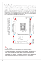
The I/O ports should be facing toward the rear of the computer case. They should line up with the holes on the I/O backplate. Mounting Screw Holes When installing the mainboard, first install the necessary mounting stands required for a mainboard on the mounting plate in your computer case. If there is an I/O back plate that came with the computer case, please replace it with the I/O backplate that came with the mainboard package. The I/O backplate should snap easily into the computer case without the need for any screws. Align the mounting plate's mounting stands with the screw holes on the mainboard and secure the mainboard with the screws provided with your computer case. The locations of the screw holes on the mainboard are shown below. For more information, please refer to the manual that came with the computer case. Important * Install the mainboard on a flat surface free from unnecessary debris. * To prevent damage to the mainboard, any contact between the mainboard cir- cuitry and the computer case, except for the mounting stands, is prohibited. * Please make sure there are no loose metal components on the mainboard or within the computer case that may cause a short circuit of the mainboard. 18
-
 1
1 -
2
-
3
-
4
-
5
-
6
-
7
-
8
-
9
-
10
-
11
-
12
-
 13
13 -
 14
14 -
 15
15 -
 16
16 -
 17
17 -
 18
18 -
 19
19 -
 20
20 -
 21
21 -
 22
22 -
 23
23 -
24
-
25
-
26
-
27
-
28
-
29
-
30
-
31
-
32
-
33
-
34
-
35
-
36
-
37
-
38
-
39
-
40
-
41
-
42
-
43
-
44
-
45
-
46
-
47
-
48
-
49
-
50
-
51
-
52
-
53
-
54
-
55
-
56
-
57
-
58
-
59
-
60
-
61
-
62
-
63
-
64
-
65
-
66
-
67
-
68
-
69
-
70
-
71
-
72
-
73
-
74
-
75
-
76
-
77
-
78
-
79
-
80
-
81
-
82
-
83
-
84
-
85
-
86
-
87
-
88
-
89
-
90
-
91
-
92
-
93
-
94
-
95
-
96
-
97
-
98
-
99
-
100
-
101
-
102
-
103
-
104
-
105
-
106
-
107
-
108
-
109
-
110
-
111
-
112
-
113
-
114
-
115
-
116
-
117
-
118
-
119
-
120
-
121
-
122
-
123
-
124
-
125
-
126
-
127
-
128
-
129
-
130
-
131
-
132
-
133
-
134
-
135
-
136
-
137
-
138
-
139
-
140
-
141
-
142
-
143
-
144
-
145
-
146
-
147
-
148
-
149
-
150
-
151
-
152
-
153
-
154
-
155
-
156
-
157
-
158
-
159
-
160
-
161
-
162
-
163
-
164
-
165
-
166
-
167
-
168
-
169
-
170
-
171
-
172
-
173
-
174
-
175
-
176
-
177
-
178
-
179
-
180
-
181
-
182
-
183
-
184
-
185
-
186
-
187
-
188
-
189
-
190
-
191
-
192
-
193
-
194
-
195
-
196
-
197
-
198
-
199
-
200
-
201
-
202
-
203
-
204
 |
 |
