MSI E350IS User Guide - Page 17
FrONT PANEl i/o CONNEcTIvITY dEsIgN GUIDE.
 |
View all MSI E350IS manuals
Add to My Manuals
Save this manual to your list of manuals |
Page 17 highlights
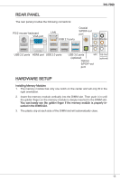
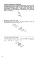
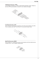
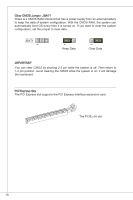
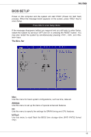
MS-7698 TPM Module Connector: JTPM1 This connector connects to a TPM (Trusted Platform Module) module. Please refer to the TPM security platform manual for more details and usages. 2.34V.36S..3tS8aVe.n15Prd0iVaob1.NlwyP2I1o.eRopG4rwoPQ.rwGeionreurornudnd 1.L3P.L5CP.LCC7P.loLRC9cP.eLka1CsPd1e1ad.CtL3drPea.dLsdCrPsedasCr&edsFdsd&sraraedt&amsasdpteaa&intpa0dinap1tian2pin3 Front Panel Connector: JFP1 The connector is for electrical connection to the front panel switches and LEDs. This is compliant with Intel® Front Panel I/O Connectivity Design Guide. PowPoewr LeEr DSwi2tc.h+41.0-6..N+8o.-Pin 1.+3.-5.-7.H+9D.RDReLseEesDrevteSdwitch Serial Port Connector: JCOM1 This connector is a 16550A high speed communication port that sends/receives 16 bytes FIFOs. You can attach a serial device. 2.S4I.ND6T.DR8S1.C0RT.NSo Pin 1.D3.CS5DO.G7Ur.RTo9uT.RnSdI 17
-
 1
1 -
2
-
3
-
4
-
5
-
6
-
7
-
8
-
9
-
10
-
11
-
 12
12 -
 13
13 -
 14
14 -
 15
15 -
 16
16 -
 17
17 -
 18
18 -
 19
19 -
 20
20 -
 21
21 -
 22
22 -
23
-
24
-
25
-
26
-
27
-
28
-
29
-
30
-
31
-
32
-
33
-
34
-
35
-
36
-
37
-
38
-
39
-
40
-
41
-
42
-
43
-
44
-
45
-
46
-
47
-
48
-
49
-
50
-
51
-
52
-
53
-
54
-
55
-
56
-
57
-
58
-
59
-
60
-
61
-
62
-
63
-
64
-
65
-
66
-
67
-
68
-
69
-
70
-
71
-
72
-
73
-
74
-
75
-
76
-
77
-
78
-
79
-
80
-
81
-
82
-
83
-
84
-
85
-
86
-
87
-
88
-
89
-
90
-
91
-
92
-
93
-
94
-
95
-
96
-
97
-
98
-
99
-
100
-
101
-
102
-
103
-
104
-
105
-
106
-
107
-
108
-
109
-
110
-
111
-
112
-
113
-
114
-
115
-
116
-
117
-
118
-
119
-
120
-
121
 |
 |
