MSI IM945GSED User Guide - Page 41
Fan Power Connector: CPUFAN1, SPI Flash ROM Pinheader: JSPI1
 |
View all MSI IM945GSED manuals
Add to My Manuals
Save this manual to your list of manuals |
Page 41 highlights
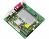
Hardware Setup SPI Flash ROM Pinheader: JSPI1 This pinheader is used to flash SPI flash ROM. JSPI1 2 10 1 9 Pin Definition Pin Description 1 VCC3_SB 3 SPI_MISO_F 5 SPI_CS0_F# 7 GND 9 SPI_HOLD# Pin Description 2 VCC3_SB 4 SPI_MOSI_F 6 SPI_CLK_F 8 GND 10 NC Fan Power Connector: CPUFAN1 The fan power connector supports system cooling fan with +12V. W hen connecting the wire to the connectors, always note that the red wire is the positive and should be connected to the +12V; the black wire is Ground and should be connected to GND. If the mainboard has a System Hardware Monitor chipset onboard, you must use a specially designed fan with speed sensor to take advantage of the CPU fan control. GND +1 2V SE NS OR CONTROL CPUFAN1 Important Please refer to the recommended CPU fans at CPU vendor's official website or consult the mainboard vendor for proper CPU cooling fan. 2-13
-
 1
1 -
2
-
3
-
4
-
5
-
6
-
7
-
8
-
9
-
10
-
11
-
12
-
13
-
14
-
15
-
16
-
17
-
18
-
19
-
20
-
21
-
22
-
23
-
24
-
25
-
26
-
27
-
28
-
29
-
30
-
31
-
32
-
33
-
34
-
35
-
 36
36 -
 37
37 -
 38
38 -
 39
39 -
 40
40 -
 41
41 -
 42
42 -
 43
43 -
 44
44 -
 45
45 -
 46
46 -
47
-
48
-
49
-
50
-
51
-
52
-
53
-
54
-
55
-
56
-
57
-
58
-
59
-
60
-
61
-
62
-
63
-
64
-
65
-
66
-
67
-
68
-
69
-
70
-
71
-
72
-
73
-
74
-
75
-
76
-
77
-
78
-
79
-
80
-
81
-
82
-
83
 |
 |
