MSI IM945GSED User Guide - Page 43
Serial Port Connector: COM1 ~ COM4, Parallel Port Header: JLPT1
 |
View all MSI IM945GSED manuals
Add to My Manuals
Save this manual to your list of manuals |
Page 43 highlights
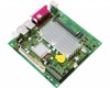
Hardware Setup Serial Port Connector: COM1 ~ COM4 (for option A, B, C, E) This connector is a 16550A high speed communications port that sends/receives 16 bytes FIFOs. You can attach a serial device to it through the optional serial port bracket. COM1~4 1 2 9 10 Pin Definition PIN SIGNAL DESCRIPTION 1 DCD Data Carry Detect 2 SIN Serial In or Receive Data 3 SOUT Serial Out or Transmit Data 4 DTR Data Terminal Ready 5 GND Ground 6 DSR Data Set Ready 7 RTS Request To Send 8 CTS Clear To Send 9 VCC_COM PowerSource Parallel Port Header: JLPT1 The mainboard provides a 26-pin header for connection to an optional parallel port bracket. The parallel port is a standard printer port that supports Enhanced Parallel Port (EPP) and Extended Capabilities Parallel Port (ECP) mode. JLPT1 26 25 2 1 PIN SIGNAL 1 RSTB# 3 PRND0 5 PRND1 7 PRND2 9 PRND3 11 PRND4 13 PRND5 PIN SIGNAL 2 AFD# 4 ERR# 6 PINIT# 8 LPT_SLIN# 10 GND 12 GND 14 GND PIN SIGNAL 15 PRND6 17 PRND7 19 ACK# 21 BUSY 23 PE 25 SLCT PIN SIGNAL 16 GND 18 GND 20 GND 22 GND 24 GND 26 KEY 2-15
-
 1
1 -
2
-
3
-
4
-
5
-
6
-
7
-
8
-
9
-
10
-
11
-
12
-
13
-
14
-
15
-
16
-
17
-
18
-
19
-
20
-
21
-
22
-
23
-
24
-
25
-
26
-
27
-
28
-
29
-
30
-
31
-
32
-
33
-
34
-
35
-
36
-
37
-
 38
38 -
 39
39 -
 40
40 -
 41
41 -
 42
42 -
 43
43 -
 44
44 -
 45
45 -
 46
46 -
 47
47 -
 48
48 -
49
-
50
-
51
-
52
-
53
-
54
-
55
-
56
-
57
-
58
-
59
-
60
-
61
-
62
-
63
-
64
-
65
-
66
-
67
-
68
-
69
-
70
-
71
-
72
-
73
-
74
-
75
-
76
-
77
-
78
-
79
-
80
-
81
-
82
-
83
 |
 |
