MSI K8NGM2 User Guide
MSI K8NGM2 Manual
 |
View all MSI K8NGM2 manuals
Add to My Manuals
Save this manual to your list of manuals |
MSI K8NGM2 manual content summary:
- MSI K8NGM2 | User Guide - Page 1
K8NGM2 Series MS-7207 (v2.X) Micro-ATX Mainboard G52-M7207X5 i - MSI K8NGM2 | User Guide - Page 2
and used in accordance with the instruction manual, may cause harmful interference to by turning the equipment off and on, the user is encouraged to try to correct the interference by the party responsible for compliance could void the user's authority to operate the equipment. Notice 2 Shielded - MSI K8NGM2 | User Guide - Page 3
Kensington Technology Group. PCMCIA and CardBus are registered trademarks of the Personal Computer Memory Card International Association. Revision History Revision V1.0 V2.0 Revision History First release for PCB 1.X with nVidia GeForce 6150/6100 & nForce 430/410 For RoHS Date Nov. 2005 Apr. 2006 - MSI K8NGM2 | User Guide - Page 4
, BIOS updates, driver updates, and other information: http://www.msi.com.tw & http://www.msi. com.tw/program/service/faq/faq/esc_faq_list.php † Contact our technical staff at: http://support.msi.com.tw Safety Instructions 1. Always read the safety instructions carefully. 2. Keep this User's Manual - MSI K8NGM2 | User Guide - Page 5
WEEE Statement v - MSI K8NGM2 | User Guide - Page 6
vi - MSI K8NGM2 | User Guide - Page 7
vii - MSI K8NGM2 | User Guide - Page 8
Support ...iv Safety Instructions ...iv WEEE Statement ...v Chapter 1. Getting Started 1-1 Mainboard Specifications 1-2 Mainboard Layout 1-5 Packing Checklist 1-6 Chapter 2. Hardware Setup 2-1 Quick Components Guide 2-2 Central Processing Unit: CPU 2-3 CPU Installation Procedures for Socket - MSI K8NGM2 | User Guide - Page 9
Front USB Connectors: JUSB1/ JUSB2 2-23 Button ...2-23 Clear CMOS Button: SW1 2-24 Slots ...2-25 PCI Express Slots 2-25 PCI (Peripheral Component Interconnect) Slots 2-25 PCI Interrupt Request Routing 2-25 Chapter 3. BIOS Setup 3-1 Entering Setup ...3-2 Control Keys 3-2 Getting Help 3-3 The - MSI K8NGM2 | User Guide - Page 10
Summary of RAID Configurations 5-2 RAID Configuration 5-3 Basic Configuration Instructions 5-3 Setting Up the NVRAID BIOS 5-3 Installing the RAID Driver (for bootable RAID Array 5-7 NVIDIA RAID Utility Installation 5-9 Installing the NVIDIA RAID Software under W indows (for Non-bootable RAID - MSI K8NGM2 | User Guide - Page 11
Audio Demo A-18 Information A-19 Using 2-, 4-, 6- & 8- Channel Audio Function A-20 Appendix B: Using the TV-Out Function (HDTV-Out Integrated B-1 Installing the TV-Out Bracket B-2 Connecting S-Video/ RCA & HDTV Cables B-3 Display Setup ...B-6 xi - MSI K8NGM2 | User Guide - Page 12
Started Chapter 1. Getting Started Getting Started Thank you for choosing the K8NGM2 Series (MS-7207 v2.X) Micro ATX mainboard. The K8NGM2 Series mainboards are based on nVidia® GeForce 6150/6100 & nVidia® nForce 430/410 chipsets for optimal system efficiency. Designed to fit the advanced AMD® K8 - MSI K8NGM2 | User Guide - Page 13
MS-7207 M-ATX Mainboard Mainboard Specifications CPU † Supports 64-bit AMD® K8 Athlon64/ Athlon64FX processor (Socket 939). † Supports 4800+ and higher CPU. (For the latest information about CPU, please visit http://www.msi.com.tw/program /produc ts /mainb oard/mb d/pro_m bd_c pu_s upport. php) - MSI K8NGM2 | User Guide - Page 14
Windows 2000 Service Pack 4 (SP4) is required. As the end user cannot boot without SP4, LAN Jack - 2 IDE ports support 4 IDE devices - 2/4 serial ATAII ports (nForce 410/430) BIOS † The mainboard BIOS provides "Plug & Play" BIOS which detects the peripheral devices and expansion cards of the board - MSI K8NGM2 | User Guide - Page 15
MS-7207 M-ATX Mainboard † The mainboard provides a Desktop Management Interface (DMI) function which records your mainboard specifications. Dimension † Micro-ATX Form Factor: 24.4cm X 24.4cm Mounting † 8 mounting holes 1394 GUID address Label (optional) MSI Reminds You... 1. Each board will be given - MSI K8NGM2 | User Guide - Page 16
Getting Started Mainboard Layout K8NGM2 Series (MS-7207 v2.X) M-ATX Mainboard 1-5 - MSI K8NGM2 | User Guide - Page 17
MS-7207 M-ATX Mainboard Packing Checklist MSI motherboard MSI Driver/Utility CD SATA Cable (Optional) Power Cable (Optional) Standard Cable for Floppy Disk Standard Cable for IDE Devices 1394 Bracket (Optional) USB Bracket (Optional) Back IO Shield User's Guide TV-out Bracket (Optional) - MSI K8NGM2 | User Guide - Page 18
Chapter 2. Hardware Setup Hardware Setup This chapter tells you how to install the CPU, memory modules, and expansion cards, as well as how to setup the jumpers on the mainboard. Also, it provides the instructions on connecting the peripheral devices, such as the mouse, keyboard, etc. W hile doing - MSI K8NGM2 | User Guide - Page 19
MS-7207 M-ATX Mainboard JCOM1, p.2-20 Back Panel I/O, p.2-10 Quick Components Guide JTV1, p.2-22 JPW1, p.2-9 CPUFAN1, p.2-15 CPU, p.2-3 DDR DIMMs, p.2-7 JCI1, p.2-18 SYSFAN1, p.2-15 NBFAN1, p.2-15 PCI Express Slots, p.2-25 PCI Slots, p.2-25 J1, p.2-19 JCD1, p.2-18 JAUD1, p.2-18 JSPDO1, p.2- - MSI K8NGM2 | User Guide - Page 20
Hardware Setup Central Processing Unit: CPU The mainboard supports AMD® Athlon64 processor. The mainboard uses a CPU socket called Socket-939 for easy CPU installation. W hen you are installing the CPU, make sure the CPU has a heat sink and a cooling fan attached on the top to prevent overheating. - MSI K8NGM2 | User Guide - Page 21
MS-7207 M-ATX Mainboard CPU Installation Procedures for Socket 939 1. Please turn off the power and unplug the power cord before installing the CPU. Sliding Plate 2. Pull the lever sideways away from the socket. Make sure to raise the lever up to a 90-degree angle. Open Lever 90 degree 3. Look - MSI K8NGM2 | User Guide - Page 22
your dealer to purchase and install them before turning on the computer. MSI Reminds You... Mainboard photos shown in this section are for demonstration of the cooler installation for Socket 939 CPUs only. The appearance of your mainboard may vary depending on the model you purchase. 1. Detach the - MSI K8NGM2 | User Guide - Page 23
MS-7207 M-ATX Mainboard 5. Position the cooling set onto the re- 7. Fasten down Lift up the intensive fixed lever. Safety Hook 9. Attach the CPU Fan cable to the CPU fan connector on the mainboard. Fixed Lever Fixed Bolt MSI Reminds You... While disconnecting the Safety Hook from the fixed bolt, - MSI K8NGM2 | User Guide - Page 24
Channel MSI Reminds You... - In dual-channel mode, make sure that you install memory modules of the same type and density on DDR DIMMs. - To enable successful system boot-up, always insert the memory modules into the DIMM1 slots first. - This mainboard DO NOT support the memory module installed - MSI K8NGM2 | User Guide - Page 25
MS-7207 M-ATX Mainboard Installing DDR Modules 1. The DDR DIMM has only one notch on the center of module. The module will only fit in the right orientation. 2. Insert the DIMM memory module vertically into the DIMM slot. Then push it in until the golden finger on the memory module is deeply - MSI K8NGM2 | User Guide - Page 26
Hardware Setup Power Supply The mainboard supports ATX power supply for the power system. This 12V power connector is used to provide power to the CPU. JPW1 3 4 1 2 Pin Definition PIN SIGNAL 1 GND 2 GND 3 12V 4 12V MSI Reminds You... 1. These two connectors connect to the ATX - MSI K8NGM2 | User Guide - Page 27
MS-7207 M-ATX Mainboard Mouse Back Panel Parallel 1394 Port L-In LAN (Optional) Keyboard DVI Port (for GeForce 6150) (optional) VGA Port USB Ports USB L-Out Ports Mic Mouse/Keyboard Connector The mainboard provides a standard PS/2® mouse/keyboard mini DIN connector for attaching a PS/2® - MSI K8NGM2 | User Guide - Page 28
of the cable is properly connected to your monitor. (refer to your monitor manual for more information.) 1 8 17 24 DVI Connector Pin Signal Assignment 1 MSI Reminds You... Please note that the DVI connector doesn't support to connect the D- Sub to DVI converter. USB Connectors The mainboard - MSI K8NGM2 | User Guide - Page 29
MS-7207 M-ATX Mainboard LAN (RJ-45) Jack:10/100 LAN (RTL8201CL) or Giga-bit LAN (VSC8201RX : optional) The mainboard provides 1 standard RJ-45 jack for connection to single Local Area Network (LAN). This LAN enables data to be transferred at 10/ 100Mbps or (1000Mbps for VSC8201RX only). You can - MSI K8NGM2 | User Guide - Page 30
there is an advanced audio application provided by Realtek ALC880 to offer support for 7.1-channel audio operation. You can use the external audio cable Line Out MIC Rear Out Center and Subwoofer Out Side Surround Out MSI Reminds You... For the advanced functions of the audio codec, please refer - MSI K8NGM2 | User Guide - Page 31
MS-7207 M-ATX Mainboard Parallel Port Connector: LPT1 The mainboard provides a 25-pin female centronic connector as LPT. A parallel port is a standard printer port that supports Enhanced Parallel Port (EPP) and Extended Capabilities Parallel Port (ECP) mode. 13 1 25 14 Pin Definition PIN - MSI K8NGM2 | User Guide - Page 32
+12V, the black wire is Ground and should be connected to GND. If the mainboard has a System Hardware Monitor chipset onboard, you must use a specially designed fan with speed sensor to take advantage of the CPU fan control. +1 2V GND SENSOR CPUFAN1 GND +1 2V SENSOR SYSFAN1 GND +1 2V SENSOR - MSI K8NGM2 | User Guide - Page 33
MS-7207 M-ATX Mainboard ATA133 Hard Disk Connectors: IDE1 & IDE2 The mainboard has a 32-bit Enhanced PCI and the hard drive up to 133 megabytes (MB) per second. The new interface is onethird IDE2 can also connect a Master and a Slave drive. MSI Reminds You... If you install two hard disks on cable, - MSI K8NGM2 | User Guide - Page 34
supports 2 SATA only) T he Mainboard s upports f our s erial ATAII c onnec tors SATA1~SATA4. SATA1~SATA4 are high-speed Serial ATAII interface ports. Each supports 2st generation serial ATA data rates of 300MB/s and is fully compliant with Serial ATA 1.0 specifications c es MSI Reminds You... Please - MSI K8NGM2 | User Guide - Page 35
MS-7207 M-ATX Mainboard CD-In Connector: JCD1 This connector is provided for CD-ROM audio. JCD1 R GND L Front Panel Audio Connector: JAUD1 The JAUD1 front panel audio connector allows you to connect to the front panel audio and is compliant with Intel® Front Panel I/O Connectivity Design Guide. - MSI K8NGM2 | User Guide - Page 36
Out NC GND SPDIF-In NC JSPDO1 Connected to JSPDO1 or JSPDI1 is by your desire. JSPDI1 SPDIF Bracket (Optional) Audio-out Connector: J1 The mainboard optionally provides a audio-out connector for you to attach a Audio-Out bracket. The Audio-Out bracket offers three audio-out jacks. Select the - MSI K8NGM2 | User Guide - Page 37
MS-7207 M-ATX Mainboard Serial Port Header: JCOM1 (Optional) The mainboard offers one 9-pin header as serial port. Set Ready 7 RTS Request To Send 8 CTS Clear To Send 9 RI Ring Indicate IEEE 1394 Connectors: J1394_1 (Optional) The mainboard provides one 1394 pin header that allows you to - MSI K8NGM2 | User Guide - Page 38
mainboard provides one front panel connector for electrical connection to the front panel switches and LEDs. The JFP1 is compliant with Intel® Front Panel I/O Connectivity Design Guide the BIOS setup to use the IR function. JIR1 is compliant with Intel® Front Panel I/O Connectivity Design Guide. - MSI K8NGM2 | User Guide - Page 39
MS-7207 M-ATX Mainboard TV-Out Connector: JTV1 (For GeForce 6150 Only, Optional) The mainboard optionally provides a TV-Out connector for you to attach a TVOut bracket that integrated HDTV-out. The TV-Out bracket offers two types of TVOut connectors: S-Video and RCA Composite connectors. Select the - MSI K8NGM2 | User Guide - Page 40
Front USB Connectors: JUSB1 / JUSB2 The mainboard provides two standard USB 2.0 pin headers JUSB1 JUSB1 or JUSB2 (yellow connectors) 9 Key (no pin) 10 USBOC USB 2.0 Bracket (Optional) MSI Reminds You... Note that the pins of VCC and GND must be connected correctly to avoid possible damage - MSI K8NGM2 | User Guide - Page 41
MS-7207 M-ATX Mainboard Button The motherboard provides the following button for you to set the computer's function. This section will explain how to change your motherboard's function through the usage of the button. Clear CMOS Button: SW1 There is a CMOS RAM on board that has a power supply from - MSI K8NGM2 | User Guide - Page 42
unplug the power supply first. Meanwhile, read the documentation for the expansion card to make any necessary hardware or software settings for the expansion card, such as jumpers, switches or BIOS configuration. PCI Slots PCI Interrupt Request Routing The IRQ, acronym of interrupt request line and - MSI K8NGM2 | User Guide - Page 43
after the memory count is the BIOS version. It is usually in the format: A7207NMS V1.0 151105 where: 1st digit refers to BIOS maker as A = AMI, W = AWARD, and P = PHOENIX. 2nd - 5th digit refers to the model number. 6th refers to the nVidia Chipset 7th - 8th digit refers to the customer as MS = all - MSI K8NGM2 | User Guide - Page 44
MS-7207 M-ATX Mainboard Entering Setup Power on the computer and the system will start POST (Power On Self Test) , only for Status Page Setup Menu and Option Page Setup Menu Restore the previous CMOS value from CMOS, only for Option Page Setup Menu Load Optimized defaults Load Fail-Safe Save all the - MSI K8NGM2 | User Guide - Page 45
BIOS Setup Getting Help After entering the Setup menu, the first menu you will see a sub-menu. If you want to return to the main menu, just press . General Help The BIOS setup program provides a General Help screen. You can call up this screen from any menu by simply pressing . The - MSI K8NGM2 | User Guide - Page 46
MS-7207 M-ATX Mainboard The Main Menu Once you enter AMI® BIOS CMOS Setup Utility, the Main Menu (Figure 1) will appear on the screen. The Main Menu allows you to select from twelve setup functions and two exit - MSI K8NGM2 | User Guide - Page 47
Defaults Use this menu to load the default values set by the mainboard manufacturer specifically for optimal performance of the mainboard. BIOS Setting Password Use this menu to set the Password. Save & Exit Setup Save changes to CMOS and exit setup. Exit Without Saving Abandon all changes and exit - MSI K8NGM2 | User Guide - Page 48
MS-7207 M-ATX Mainboard Standard CMOS Features The items in Standard CMOS week, from Sun to Sat, determined by BIOS. Read-only. month The month from Jan year The year can be adjusted by users. Time (HH:MM:SS) This to select the hard disk drive type. The specification of hard d i s k drive will - MSI K8NGM2 | User Guide - Page 49
BIOS (0-4) for the IDE devices that the onboard IDE interface supports. Modes 0 through 4 provide successively increased performance. In [Mode 4]. DMA Mode This item allows you to enable or disable the DMA (Direct Memory Access) mode. Setting options: [Auto], [SWDMA0], [SWDMA1], [SWDMA2], [MWDMA0], - MSI K8NGM2 | User Guide - Page 50
MS-7207 M-ATX Mainboard Hard Disk S.M.A.R.T. This allows you to activate the S.M.A.R.T. (Self- sub-menu of each item: Usage Memory This item shows the memory status (read only). **CPU Information** AMD Sempron(tm) Processor/CPU ID The two items show the CPU related information of your system (read - MSI K8NGM2 | User Guide - Page 51
POST messages at boot. Boot Sector Protection This function protects the BIOS from accidental corruption by unauthorized users or computer viruses. W hen enabled, the BIOS' data cannot be changed when attempting to update the BIOS with a Flash utility. To successfully update the BIOS, you'll need - MSI K8NGM2 | User Guide - Page 52
MS-7207 M-ATX Mainboard IOAPIC Function This field is used to enable or disable the APIC (Advanced Programmable Interrupt Controller). Due to compliance with PC2001 design guide -Processor Specification) version to be used for the operating system. You need to select the MPS version supported by - MSI K8NGM2 | User Guide - Page 53
BIOS Setup Advanced Chipset Features MSI Reminds You... Change these settings only if you are familiar with the chipset. Memclock Mode Users can place an artificial memory clock on the system. Please note that memory is prevented from running faster than this frequency. Setting options:[Auto], [ - MSI K8NGM2 | User Guide - Page 54
Flash utility. To successfully update the BIOS, you will need to disable this Flash Protection function. Setting options: [Enabled], [Disabled]. Primary Graphics Adapter This setting specifies which VGA card is your primary graphics adapter. Setting options are: [PCI Express] The system initializes - MSI K8NGM2 | User Guide - Page 55
BIOS Setup TV Mode Support This item allows you to select the TV display mode. Setting options: [NTSC_M], [NTSC_J], [PAL_M], [PAL_BDGHI], [PAL_N], [PAL_NC], [Default]. OnChip VGA Trap Enable Setting options: [Enabled] and [Disabled]. CPU-LDT Frequency, MHz This setting shows the current CPU Front - MSI K8NGM2 | User Guide - Page 56
MS-7207 M-ATX Mainboard Integrated Peripherals USB 1.1 Controller This setting disables/enables the USB 1.1 controller. Setting options: [Enabled], [Disabled]. USB 2.0 Controller Set to [Enabled] if you need to use any USB 2.0 device in the operating system that does not support or have any USB 2.0 - MSI K8NGM2 | User Guide - Page 57
BIOS Setup Onboard IEEE1394 Controller This setting allows you to enable/disable the onboard IEEE 1394 controller. Setting options: [Enabled], [Disabled]. AZALIA AUDIO Select Enabled to use the audio capabilities of your system. Setting options: [Auto], [Disabled]. M AC LAN the system board and you - MSI K8NGM2 | User Guide - Page 58
MS-7207 M-ATX Mainboard IDE Devices Configuration Press to enter the sub-menu and the following screen appears: PCI IDE BusM aster This item allows you to enable/ disable the PCI options: [Enabled], [Disabled]. nVidia RAID Setup Press to enter the sub-menu and the - MSI K8NGM2 | User Guide - Page 59
MSI Reminds You... S3-related functions described in this section are available only when your BIOS supports no system context is lost (CPU or chipset) and hardware maintains all memory that remains powered while most other hardware components turn off to save energy. The information stored in memory - MSI K8NGM2 | User Guide - Page 60
MS-7207 M-ATX Mainboard Power Button Function This feature allows users to configure the Power Button function. Settings are: this item will decrease the frequency of the CPU when the CPU is overheat. Setting options: [Disabled], [Enabled]. Manual Throttle Ratio The item specifies the percentage of - MSI K8NGM2 | User Guide - Page 61
]. Specific Key for PowerOn If PS/2 Device Wakeup is set to [Enabled], then you can set a key in the field for the PS/2 keyboard to power on the system. Resume by M AC LAN An input signal from the LAN awakens the system from a soft off state. Setting options: [Disabled], [Enabled]. Resume by PCI - MSI K8NGM2 | User Guide - Page 62
MS-7207 M-ATX Mainboard PNP/PCI Configurations This section describes configuring the PCI bus system and PnP (Plug & Play) feature. PCI, or Peripheral Component Interconnect, is a system which allows I/O devices to operate at speeds nearing the speed the CPU itself uses when communicating with its - MSI K8NGM2 | User Guide - Page 63
Memory Access) channel is using. The settings determine if AMIBIOS should remove a DMA from the available DMAs passed to devices that are configurable by the system BIOS. The available DMA pool is determined by reading the ESCD NVRAM. If more DMAs must be removed from the pool, the end user can - MSI K8NGM2 | User Guide - Page 64
MS-7207 M-ATX Mainboard MSI Reminds You... IRQ (Interrupt Request) lines are system resources allocated to I/O devices. When an I/O device needs to gain receiving the signal, when the operating system is ready, the system will interrupt itself and perform the service required by the I/O device. 3-22 - MSI K8NGM2 | User Guide - Page 65
], [Reset], [Disabled]. Smart Fan Target Temperature The mainboard provides the Smart Fan system which can control the fan speed automatically depending on the current temperature to keep it with in a specific range. System/CPU Temperature, SYSTEM FAN Speed, CPU Vcore, +12.0V, +5.0V, +3.3V, Battery - MSI K8NGM2 | User Guide - Page 66
MS-7207 M-ATX Mainboard Cell_Menu The items in Cell Menu includes some important settings of CPU, PCIE, DRAM. MSI Reminds You... Change these settings only if you are familiar with the chipset. Current CPU Clock This field shows the current clocks of CPU. Read-only. Cool'n'Quiet This feature is - MSI K8NGM2 | User Guide - Page 67
BIOS Setup Adjust DDR the sub-menu and the following screen appears: W hen the motherboard's clock generator pulses, the extreme values (spikes) of the pulses that the spikes of the pulses are reduced to flatter curves. CPU Spread Spectrum Setting options: [Disabled], [Center Spread], [Down Spread - MSI K8NGM2 | User Guide - Page 68
MS-7207 M-ATX Mainboard Load Fail-Safe/Optimized Defaults The two options on the main menu allow users to restore all of the BIOS settings to the default Fail-Safe or Optimized values. The Optimized Defaults are the default values set by the mainboard manufacturer specifically for optimal - MSI K8NGM2 | User Guide - Page 69
. The password typed now will replace any previously set password from CMOS memory. You will be prompted to confirm the password. Retype the password and press . You may also press to abort the selection and not enter a password. To clear a set password, just press when - MSI K8NGM2 | User Guide - Page 70
that MSI has spent much research and efforts to develop, helps users to LAN settings. Moreover, with this unique utility, you will be able to activate the MSI well-known feature 'Live Update', which makes it easier to update the BIOS/drivers online, and to monitor the system hardware status (CPU - MSI K8NGM2 | User Guide - Page 71
MS-7207 MM-SAITFXeaMtuarienboard Main Before using this utility, it is required to have all the integrated peripherals/cards (LAN card, W ireless LAN card, MegaStick... etc.) and all the necessary drivers (onboard LAN driver, audio driver, CoreCenter, Live Update... etc.) installed correctly. The - MSI K8NGM2 | User Guide - Page 72
as the authentication encryption... etc. Live Update You can take advantage of Live Update to detect and update BIOS and drivers online. PC Alert You can take advantage of the power-on, power-off and restarting features. MSI Reminds You... Click on back button in every sub-menu and it will bring you - MSI K8NGM2 | User Guide - Page 73
MS-7207 MM-SAITFXeaMtuarienboard H/W Diagnostic In the H/W Diagnostic sub-menu, you can see the information, status and note of each DigiCell. You may double check the connection and installation of the item marked as gray. You may also click on the Mail to MSI button to send your questions or - MSI K8NGM2 | User Guide - Page 74
for details. This icon indicates the information and connection status of onboard LAN, which is read-only. The second icon indicates the wireless connection. Card Mode dialogue box (see the image on p.4-8). Please note that it is only available when the Software Access Point is set to WLAN Card Mode - MSI K8NGM2 | User Guide - Page 75
MS-7207 your usage. The default software access point mode is set to WLAN Card Mode. For more advanced security settings and channels switching, click on " enables users on a wireless LAN to access an existing wired network, allowing wireless users to take advantage of the wired networks resources, - MSI K8NGM2 | User Guide - Page 76
are getting on Internet in office, usually the LAN card will automatically get the IP this computer uses. In this case you don't have to enable this function. SSID Means Service Set Identifier, a unique name shared among all points in a wireless network. It must be identical for all points in the - MSI K8NGM2 | User Guide - Page 77
MS-7207 MM-SAITFXeaMtuarienboard enable this feature, only PCs with MAC address located in Association Control List can connect to the wireless LAN. MAC Address MAC stands for Media Access Control. A MAC address is the hardware address of a device connected to a network. Security This option allows - MSI K8NGM2 | User Guide - Page 78
driver online. Live Utility - Updates the utilities online. If the product you purchased does not support any of the functions listed above, a "sorry" message is displayed. For more information on the update instructions, insert the companion CD and refer to the "Live Update Guide" under the "Manual - MSI K8NGM2 | User Guide - Page 79
MS-7207 MM-SAITFXeaMtuarienboard MEGA STICK In the MEGA STICK sub-menu, you can configure the settings of MSI MEGA STICK and the media files (*. save the file in the plain text file format in the \\Program files\MSI\DigiCell\MyMusic.txt for your reference. The MyMusic.txt file is with the following information - MSI K8NGM2 | User Guide - Page 80
Introduction to DigiCell There is also a toolbar for you to execute some basic function, like play, stop, pause, previous/next song, song info and volume adjust. There is also a scroll bar on the top for you to forward/rewind. previous pause next forward/rewind bar stop play song's - MSI K8NGM2 | User Guide - Page 81
MS-7207 MM-SAITFXeaMtuarienboard Non-Unicode programs supported If you are using an operating system the file names display incorrectly. However, you can install the Supplemental Language Support provided by Microsoft to solve this problem. You need to have your Microsoft Setup CD prepared in the CD - MSI K8NGM2 | User Guide - Page 82
Introduction to DigiCell 3. Then go to the [Advanced] tab and select the language you want to be supported (the language of the filename in the MegaStick) from the dropdown list in the [Language for non-Unicode programs], then click [Apply]. The system will - MSI K8NGM2 | User Guide - Page 83
MS-7207 top of the screen it shows the current PC hardware status such as the CPU & system temperatures. On the middle of the screen it shows the current fan speeds. When you click the MENU button, an menu list will appear for users to select. Click the Sys Info/ W MI Info, it will show the system - MSI K8NGM2 | User Guide - Page 84
the system will start to count down to restart. Click "OK" to restart the computer right away or click "Later" to restart your computer later. MSI Reminds You... Please note that the new setting will not take effect until you restart your computer. 4-15 - MSI K8NGM2 | User Guide - Page 85
MS-7207 MM-SAITFXeaMtuarienboard Power Off / Restart You may configure the time (in programs, or you can right-click on the selected program and click Delete. delete the added program MSI Reminds You... You can also enable the Every turn on function, which will enable the specified program(s) - MSI K8NGM2 | User Guide - Page 86
everytime when you boot up your computer. 2. If there are multi users using the same computer and you'd like to power on the computer automatically with one specific user. Enable Auto Login Enable this setting if you want to use the Auto Login feature. It supports the following operating systems - MSI K8NGM2 | User Guide - Page 87
RAID Introduction Chapter 6. nVidia RAID Introduction nVidia RAID Introduction NVIDIA brings Redundant Array of Independent Disks (RAID) technology-which is used by the world's leading businesses-to the common PC desktop. This technology uses multiple - MSI K8NGM2 | User Guide - Page 88
M S-7207 M -ATX M ainboard Introduction System Requirement Operating System Support NVRAID supports the following operating systems: W indows XP W indows 2000 Professional RAID Arrays NVRAID supports the following types of RAID arrays described in this section: RAID 0: RAID 0 defines a disk - MSI K8NGM2 | User Guide - Page 89
desired RAID array. 3. Boot from the W indows CD, use the floppy disk that has the RAID driver to copy and install the nForce RAID software. (Check p.6-7 for details.) 4. Initialize the NVRAID Array Disks. Setting Up the NVRAID BIOS Be sure to enable the nVidia RAID Function in nVidia RAID Setup of - MSI K8NGM2 | User Guide - Page 90
M S-7207 M -ATX M ainboard of each hard disk is given in the Loc (location) columns of the Free Disks and Array Disks lists. In the example above, 1.0.M means the hard Channel 2, controller 0, Master 2.1.M Channel 2, controller 1, Master MSI Reminds You... There is no such thing as Slave drive - MSI K8NGM2 | User Guide - Page 91
nVIDIA RAID Introduction Using the Define a New Array Window If necessary, press the and [128 KB]. • Assigning the Disks The disks that you enabled from the RAID Config BIOS setup page appear in the Free Disks block. These are the drives that are available for use as RAID array disks. To designate - MSI K8NGM2 | User Guide - Page 92
back to the previous window and then press Ctrl+X to exit the RAID setup. Now that the RAID setup has been configured from the RAID BIOS, the next step is to configure and load NVRAID drivers under W indows, as explained in "Installing the NVIDIA RAID Software Under W indows" on p5-9. 5-6 - MSI K8NGM2 | User Guide - Page 93
, press S, then press Enter. The W indows Setup screen appears as below: MSI Reminds You... Please follow the instruction below to make an nVIDIA Serial ATA RAID driver for yourself. 1. Insert the MSI CD into the CD-ROM drive. 2. Click the "Browse CD" on the Setup screen. 3. Copy all the contents - MSI K8NGM2 | User Guide - Page 94
out the floppy. 5. Follow the instructions on how to install W indows XP. After W indows XP is completely installed, it is recommended that you install the the RAID management tool. MSI Reminds You... Each time you add a new hard drive to a RAID array, the RAID driver will have to be installed under - MSI K8NGM2 | User Guide - Page 95
. Make sure that the "NVIDIA IDE Driver" is selected. MSI Reminds You... You must install the NVIDIA IDE driver in order to enable NVIDIA RAID. If you do not install the NVIDIA IDE driver, NVIDIA RAID will not be enabled. 3. Click Next and then follow the instructions. 4. After the installation is - MSI K8NGM2 | User Guide - Page 96
M S-7207 M -ATX M ainboard Initializing and Using the Disk Array The RAID array is now ready to be initialized under W indows. 1. Launch Computer Management by clicking "Start" --> " - MSI K8NGM2 | User Guide - Page 97
nVIDIA RAID Introduction 5. Check the disk in the list if you want to make the array a dynamic disk, then click Next. The Completing the Initialize and - MSI K8NGM2 | User Guide - Page 98
.exe (the default location of NvRaidMan.exe is in \\nVidia\System\C51+MCP51\IDE\Win2k or XP\raidtool\ of the setup CD accompanied with your mainboard). The RAID configuration information appears in the right-side pane, as shown below. 5-12 MSI Reminds You... The information in the figures in this - MSI K8NGM2 | User Guide - Page 99
process is automatic and doesn't require any user interaction. For example, if you have a system with four hard disks where one disk is used to boot the OS, two hard drives are set up in a mirrored array, and a fourth hard disk is set up as a free disk, then if one of the mirrored - MSI K8NGM2 | User Guide - Page 100
M S-7207 M -ATX M ainboard Assigning a Dedicated Disk To mark a disk as dedicated, or reserve it for use by a specific array, Step 1: Mark the Disk as a Free Disk 1. Enter the system BIOS setup and make sure that the drive that you want to mark as free is RAID enabled. 2. Boot into W indows and run - MSI K8NGM2 | User Guide - Page 101
the disk that will be designated to the mirror array. 5. Click Next. The Completing the NVIDIA Spare Disk Allocation page appears. 6. Click Finish. As shown in figure below, the ST380011A drive is now a dedicated free disk in the mirrored array. If a system crash occurs that causes any of the two - MSI K8NGM2 | User Guide - Page 102
M S-7207 M -ATX M ainboard Removing a Dedicated Disk Once a dedicated disk has been assigned to a particular array, it can be removed at any time. To remove the disk, - MSI K8NGM2 | User Guide - Page 103
user must back up the data, delete the array, re-boot the PC, and then reconfigure the new array. NVIDIA RAID allows the end user Principles NVIDIA RAID includes extensive support for 0+1 to RAID 1 - From RAID 5 to 1 Specific Morphing Requirements The following table lists the disk requirements for - MSI K8NGM2 | User Guide - Page 104
M S-7207 M -ATX M ainboard From RAID 0+1 RAID 5 To RAID 0 RAID 1 RAID 0+1 RAID 5 RAID 0 system safely and without causing problems for the RAID software. For example, when a drive in a mirrored array fails, the user can launch the Hot Plug Array W izard which instructs the user as to when a drive - MSI K8NGM2 | User Guide - Page 105
nVIDIA RAID Introduction 2 Click Next and the following screen shot will appear: disks. Initialization of newly configured RAID arrays is recommended to ensure consistency and reliable performance on any supported fault tolerant array such asRAID 5, RAID 0, and RAID 0+1. Use this feature only if you - MSI K8NGM2 | User Guide - Page 106
M S-7207 M -ATX M ainboard 1 From the NVRAIDMAN window, right click on any available free disk and select Create Array as show in Figure Stripe Size is set to its default value of 64K, then click Next. 5 At the Free Disk Selection page, select the two drives that you want to Mirror and click Next. - MSI K8NGM2 | User Guide - Page 107
RAID Introduction 8 Click OK. The Clearing System Data screen appears again with the Initialize Array check box checked as shown below. 9 Click Next, then click Finish at the Completing the NVIDIA Create Array W izard screen. The NVRAIDMAN windows shows the created RAID array as shown below. The - MSI K8NGM2 | User Guide - Page 108
M S-7207 M Instructions After creating a mirrored array, you can rebuild the array using the following steps: 1 Go to Windows and run the NVIDIA RAID Management utility. The picture below shows an example of a system with one mirrored array and two free disks. 2. Right - MSI K8NGM2 | User Guide - Page 109
Disk Selection page appears. 5. Select the drive that you want to rebuild by clicking it from the list, then click Next. The Completing the NVIDIA Rebuild Array page appears. 6. Click Finish. The array rebuilding starts after a few seconds, and a small pop-up message appears towards the bottom right - MSI K8NGM2 | User Guide - Page 110
M S-7207 M -ATX M ainboard During the rebuilding process, the NVRAID Management utility screen shows a mirrored array using two 34.48 GB drives while having two Free Disks each 55.90 GB large. To use one of these available free disks to rebuild your array, follow the same steps as explained in " - MSI K8NGM2 | User Guide - Page 111
nVIDIA RAID Introduction Synchronizing a RAID Array Synchronizing an array will force a rebuild of redundancy or parity. The operation is applicable to any fault tolerant array such - MSI K8NGM2 | User Guide - Page 112
M S-7207 M -ATX M ainboard Usind Disk Alert The RAID manager application includes indows system tray. Click the popup box to view the manufacturer-provide bitmap image of the system motherboard. The image shows the hard drive connector ports and provides a visual indication of the location and - MSI K8NGM2 | User Guide - Page 113
to Realtek ALC880 The mainboard is equipped with Realtek ALC880 chip, which provides support for 8-channel audio output, including 2 Front, 2 Rear, 2 Side, 1 Center and 1 Subwoofer channel. ALC880 allows the board to attach 2, 4, 6 or 8 speakers for better surround sound effect. The section will - MSI K8NGM2 | User Guide - Page 114
MS-7207 M-ATX Mainboard Installing the Audio Driver You need to install the driver for Realtek ALC880 codec to function properly before you can get access to 2-, 4-, 6- or 8- channel audio operations. Follow the procedures described below to install the drivers for different operating systems. - MSI K8NGM2 | User Guide - Page 115
Introduction to Realtek ALC880 3. Click Next to install the Realtek High Definition Audio Driver. 4. Click Finish to restart the system. Click here Select this option Click here A-3 - MSI K8NGM2 | User Guide - Page 116
MS-7207 M-ATX Mainboard Software Configuration After installing the audio driver, you are able to use the 2-, 4-, 6- or 8- channel audio feature Configuration. It is also available to enable the audio driver by clicking the Azalia HD Sound Effect Manager from the Control Panel. Double click A-4 - MSI K8NGM2 | User Guide - Page 117
like from the Environment list. Load EQ Setting Reset EQ Setting EQ Setting On/Off Save Preset Delete EQ Setting You may choose the provided sound effects, and the equalizer will adjust automatically. If you like, you may also load an equalizer setting or make a new equalizer setting to save as - MSI K8NGM2 | User Guide - Page 118
MS-7207 M-ATX Mainboard Equalizer Selection Equalizer frees users from default settings; users may create their owned to the default setting. Enable / Disable To disable, you can temporarily stop the sound effect without losing the settings. Load W henever you would like to use preload settings - MSI K8NGM2 | User Guide - Page 119
Frequently Used Equalizer Setting Realtek recognizes the needs that you might have. By leveraging our long experience at audio field, Realtek HD Audio Sound Manager provides you certain optimized equalizer settings that are frequently used for your quick enjoyment. [How to Use It] Other than the - MSI K8NGM2 | User Guide - Page 120
MS-7207 M-ATX Mainboard Mixer In the Mixer part, you may adjust the volumes of the rear and front panels individually. 1. Volume You can adjust the volume of the speakers that you pluged in front or rear panel by select the Realtek HD Audio rear output or Realtek HD Audio front output items. MSI - MSI K8NGM2 | User Guide - Page 121
Introduction to Realtek ALC880 W hen you are playing the first audio source (for example: use W indows Media Player to play DVD/VCD), the output will be played from the rear panel, which is the default setting. Then you must to select the Realtek HD Audio front output from the scroll list first, and - MSI K8NGM2 | User Guide - Page 122
MS-7207 M-ATX Mainboard 3. Playback control Tool Mute Playback device This function is to let you freely decide which ports to output the sound. And this is essential when multistreamingplayback enabled. Mute You may choose to mute single or multiple volume controls or to completely mute sound - MSI K8NGM2 | User Guide - Page 123
to connect your microphone to the front audio panel. You may control the microphone volume by Mic Volume or front mic-in on the mixer. MSI Reminds You... Only the speakers that plugged into the Line-Out jack (the green ne) on the back panel will be functional when you intend - MSI K8NGM2 | User Guide - Page 124
MS-7207 M-ATX Mainboard AudioIO In e. 8CH Speaker for 8-Speaker Output Realtek HD Audio Manager frees you from default speaker settings. Different from before, for pink to pink, the way that you used to do, Audio I/O would guide you to other right jacks that can also serve as microphone / speaker / - MSI K8NGM2 | User Guide - Page 125
Introduction to Realtek ALC880 Correct Message Assume to plug a headphone in the Green jack at back panel. The icon beside green jack become visible and the dialogue "connected device" pops up. Check the headphone, then click OK. As soon as OK is clicked, the icon beside green jack becomes " - MSI K8NGM2 | User Guide - Page 126
MS-7207 M-ATX Mainboard Global Connector Settings Click to access global connector settings. 1. Mute rear panel when front headphone plugged in Once this item is checked, whenever front headphone - MSI K8NGM2 | User Guide - Page 127
Introduction to Realtek ALC880 S/PDIF Short for Sony/Philips Digital Interface, a standard audio file transfer format. S/ PDIF allows the transfer of digital audio signals from one device to another without having to be converted first to an analog format. Maintaining the viability of a digital - MSI K8NGM2 | User Guide - Page 128
MS-7207 M-ATX Mainboard Test Speakers You can select the speaker by clicking it to test its functionality. The one you select will light up and make testing sound. If any speaker fails to make sound, then check whether the cable is inserted firmly to the connector or replace the bad speakers - MSI K8NGM2 | User Guide - Page 129
Introduction to Realtek ALC880 Microphone In this tab you may set the function of the microphone. Select the Noise Suppression to remove the possible noise during recording, or select Acoustic Echo Cancelltion to cancel the acoustic echo druing recording. A-17 - MSI K8NGM2 | User Guide - Page 130
MS-7207 M-ATX Mainboard 3D Audio Demo In this tab you may adjust your 3D positional audio before playing 3D audio applications like gaming. You may also select different environment to choose the most suitable environment you like. A-18 - MSI K8NGM2 | User Guide - Page 131
Introduction to Realtek ALC880 Information In this tab it provides some information about this HD Audio Configuration utility, including Audio Driver Version, DirectX Version, Audio Controller & Audio Codec. You may also select the language of this utility by choosing from the Language list. Also - MSI K8NGM2 | User Guide - Page 132
MS-7207 M-ATX Mainboard Using 2-, 4-, 6- & 8- Channel Audio Function Connecting the Speakers W hen you have set the Multi-Channel Audio Function mode properly in the software utility, connect your speakers - MSI K8NGM2 | User Guide - Page 133
Introduction to Realtek ALC880 n 4-Channel Mode for 4-Speaker Output 1 4 2 5 3 6 4-Channel Analog Audio Output Description: Connect two speakers to back panel's Line Out connector and two speakers to the real-channel Line Out connector. 1 Line In 2 Line Out (Front channels) 3 MIC 4 Line Out - MSI K8NGM2 | User Guide - Page 134
MS-7207 M-ATX Mainboard n 6-Channel Mode for 6-Speaker Output 1 4 2 5 3 6 6-Channel Analog Audio Output 1 Line In Description: Connect two speakers to back panel's Line Out connector, two speakers to the - MSI K8NGM2 | User Guide - Page 135
Introduction to Realtek ALC880 n 8-Channel Mode for 8-Speaker Output 1 4 2 5 3 6 8-Channel Analog Audio Output 1 Line Out (Side channels) 2 Line Out (Front channels) 3 MIC 4 Line Out (Rear channels) 5 Line Out (Center and Subwoofer channel) 6 Side Surround Out (Side channels) Description: - MSI K8NGM2 | User Guide - Page 136
TV-Out bracket and configure the display settings. Note that the TV-Out bracket works with the onboard graphic core. Do not insert any VGA card into the slot while using the TV-Out bracket. B-1 - MSI K8NGM2 | User Guide - Page 137
MS-7207 M-ATX Mainboard Installing the TV-Out Bracket 1. Take out the TV-Out bracket. TV-Out Bracket Foolproof design TV-Out Connector TV-Out Connector (RCA Composite) (S-Video) 2. Locate the TV-out connector (JTV1) on the mainboard. 3. Connect the TV-Out bracket to the connector. Align the - MSI K8NGM2 | User Guide - Page 138
Using the TV-Out Function Connecting S-Video/ RCA & HDTV Cables Connecting S-Video cable 1. Connect one end of the S-Video cable to the TV-Out(S) connector. S-Video cable 2. Connect the other end of the S-Video cable to the TV. B-3 - MSI K8NGM2 | User Guide - Page 139
MS-7207 M-ATX Mainboard Connecting RCA cable 1. Connect one end of the RCA cable to the blue connector of the TV-Out cable. The RCA cable usually comes with three connecotrs on both ends. The white or red connector is for audio while the yellow one is for video. RCA cable W hite (Audio) Red (Audio - MSI K8NGM2 | User Guide - Page 140
Using the TV-Out Function Connecting HDTV cable 1. Connect one end of the HDTV cable to the TV-Out(C) connectors. The HDTV cable usually comes with three connecotrs on both ends. HDTV cable Green Red Blue Blue Green Red 2. Connect the other end of the HDTV cable to the HDTV. B-5 - MSI K8NGM2 | User Guide - Page 141
MS-7207 M-ATX Mainboard Display Setup The following procedures describe display setup using W indows XP. Windows 2000/ME/9X screens are slightly different but the procedures are the same - MSI K8NGM2 | User Guide - Page 142
Using the TV-Out Function 4. In the nView tab, click Device Set- tings to set up or change settings related to the output device used for the current display. click here 5. In the Device Selection tab, first click TV and then Change Format. click here B-7 - MSI K8NGM2 | User Guide - Page 143
MS-7207 M-ATX Mainboard 6. Select your local TV format. 7. (refer to Step 4) Under Device Settings, click Device Adjustments. In the Screen Adjustment tab, use the 4-way navigation keys to adjust the screen position. Click Default to restore the factory setup value. 8. Click OK to exit. B-8
-
 1
1 -
 2
2 -
 3
3 -
 4
4 -
 5
5 -
 6
6 -
 7
7 -
8
-
9
-
10
-
11
-
12
-
13
-
14
-
15
-
16
-
17
-
18
-
19
-
20
-
21
-
22
-
23
-
24
-
25
-
26
-
27
-
28
-
29
-
30
-
31
-
32
-
33
-
34
-
35
-
36
-
37
-
38
-
39
-
40
-
41
-
42
-
43
-
44
-
45
-
46
-
47
-
48
-
49
-
50
-
51
-
52
-
53
-
54
-
55
-
56
-
57
-
58
-
59
-
60
-
61
-
62
-
63
-
64
-
65
-
66
-
67
-
68
-
69
-
70
-
71
-
72
-
73
-
74
-
75
-
76
-
77
-
78
-
79
-
80
-
81
-
82
-
83
-
84
-
85
-
86
-
87
-
88
-
89
-
90
-
91
-
92
-
93
-
94
-
95
-
96
-
97
-
98
-
99
-
100
-
101
-
102
-
103
-
104
-
105
-
106
-
107
-
108
-
109
-
110
-
111
-
112
-
113
-
114
-
115
-
116
-
117
-
118
-
119
-
120
-
121
-
122
-
123
-
124
-
125
-
126
-
127
-
128
-
129
-
130
-
131
-
132
-
133
-
134
-
135
-
136
-
137
-
138
-
139
-
140
-
141
-
142
-
143
 |
 |
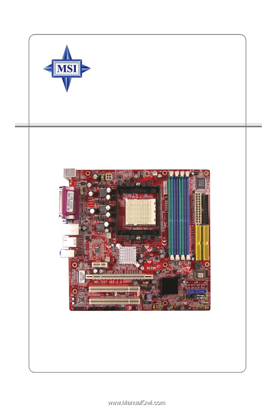
MS-7207 (v2.X) Micro-ATX Mainboard
K8NGM2 Series
G52-M7207X5