MSI K9N SLI-F User Guide - Page 37
D-Bracket, Connector: JDB1 - v 2 specs
 |
UPC - 816909043235
View all MSI K9N SLI-F manuals
Add to My Manuals
Save this manual to your list of manuals |
Page 37 highlights
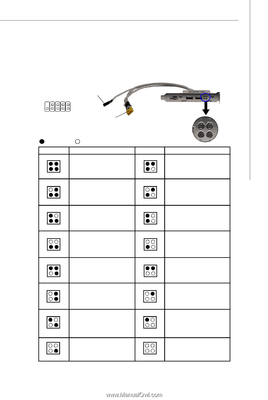
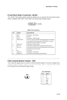
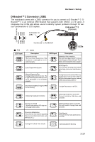
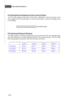
Hardware Setup D-Bracket™ 2 Connector: JDB1 The mainboard comes with a JDB1 connector for you to connect to D-Bracket™ 2. DBracket™ 2 is an external USB Bracket that supports both USB1.1 & 2.0 specs. It integrates four LEDs and allows users to identify system problems through 16 vari- ous combinations of LED signals. D-Bracket™ 2 (Optional) DBG1 DBG1 DBG3 DBG4 (No pin)Key Connected to JDB1 9 1 10 2 DBR1 DBR2 DBR3 DBR4 NC Red LED Signal 1 2 3 4 Connected to JUSB1/2/3 Green 1 2 3 4 LEDs Description LED Signal Description System Power ON The D-LED will hang here if the 1 processor is damaged or not in- 3 stalled properly. Initializing Video Interface 2 This will start detecting CPU clock, 4 checking type ofvideo onboard. Then, detect and initializethe video adapter. 1 2 EarlyChipset Initialization 3 4 BIOS Sign On 1 2 This will start showing information 3 4 about logo, processor brand name, etc... Memory Detection Test Testing Base and Extended Memory 1 2 Testing onboard memory size. The 1 2 Testing base memory from 240K to 3 D-LED will hang if the memory mod4 ule is damaged or not installed 3 4 640K and extended memory above 1MB using various patterns. properly. 1 2 Decompressing BIOS image to RAM 1 2 Assign Resources to all ISA. 3 4 for fast booting. 3 4 1 2 Initializing Keyboard Controller. 1 2 Initializing Hard Drive Controller This will initialize IDE drive and 3 4 3 4 controller. 1 2 Testing VGA BIOS 1 2 Initializing Floppy Drive Controller This will start writing VGA sign-on This will initialize Floppy Drive and 3 4 message to the screen. 3 4 controller. 1 3 Processor Initialization 2 This will show information regarding 1 4 the processor (like brand name, sys- 3 tem bus, etc...) 2 BootAttempt This will set low stack and boot via 4 INT 19h. 1 2 1 2 3 Testing RTC (Real Time Clock) 4 3 4 Operating System Booting 2-19
-
 1
1 -
2
-
3
-
4
-
5
-
6
-
7
-
8
-
9
-
10
-
11
-
12
-
13
-
14
-
15
-
16
-
17
-
18
-
19
-
20
-
21
-
22
-
23
-
24
-
25
-
26
-
27
-
28
-
29
-
30
-
31
-
 32
32 -
 33
33 -
 34
34 -
 35
35 -
 36
36 -
 37
37 -
 38
38 -
 39
39 -
 40
40 -
 41
41 -
 42
42 -
43
-
44
-
45
-
46
-
47
-
48
-
49
-
50
-
51
-
52
-
53
-
54
-
55
-
56
-
57
-
58
-
59
-
60
-
61
-
62
-
63
-
64
-
65
-
66
-
67
-
68
-
69
-
70
-
71
-
72
-
73
-
74
-
75
-
76
-
77
-
78
-
79
-
80
-
81
-
82
-
83
-
84
-
85
-
86
-
87
-
88
-
89
-
90
-
91
-
92
-
93
-
94
-
95
-
96
-
97
-
98
-
99
-
100
-
101
-
102
-
103
-
104
-
105
-
106
-
107
-
108
-
109
-
110
-
111
-
112
-
113
-
114
-
115
-
116
-
117
-
118
-
119
-
120
-
121
-
122
 |
 |