MSI K9N2GM User Guide - Page 27
Serial ATA Connector: SATA1~6, Parallel Port Header: JLPT1
 |
View all MSI K9N2GM manuals
Add to My Manuals
Save this manual to your list of manuals |
Page 27 highlights
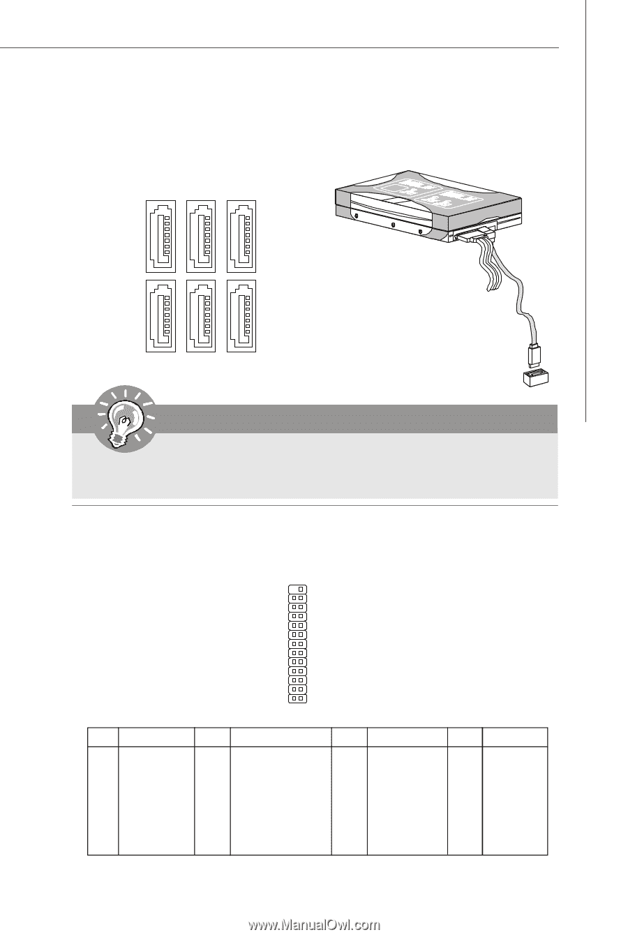
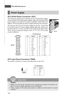
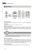
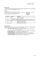
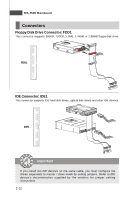
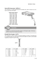
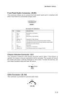
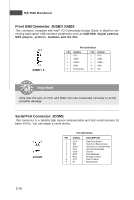
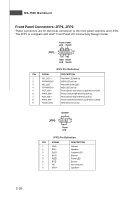
Hardware Setup Serial ATA Connector: SATA1~6 This connector is a high-speed Serial ATA interface port. Each connector can connect to one Serial ATA device. SATA2 SATA3 SATA5 SATA1 SATA4 SATA6 Important Please do not fold the Serial ATA cable into 90-degree angle. Otherwise, data loss may occur during transmission. Parallel Port Header: JLPT1 This connector is used to connect an optional parallel port bracket. The parallel port is a standard printer port that supports Enhanced Parallel Port (EPP) and Extended Capabilities Parallel Port (ECP) mode. 26 25 JLPT1 PIN SIGNAL 1 RSTB# 3 PRND0 5 PRND1 7 PRND2 9 PRND3 11 PRND4 13 PRND5 2 1 PIN SIGNAL 2 AFD# 4 ERR# 6 PINIT# 8 LPT_SLIN# 10 GND 12 GND 14 GND PIN SIGNAL 15 PRND6 17 PRND7 19 ACK# 21 BUSY 23 PE 25 SLCT PIN SIGNAL 16 GND 18 GND 20 GND 22 GND 24 GND 26 Key (No Pin) 2-13
-
 1
1 -
2
-
3
-
4
-
5
-
6
-
7
-
8
-
9
-
10
-
11
-
12
-
13
-
14
-
15
-
16
-
17
-
18
-
19
-
20
-
21
-
 22
22 -
 23
23 -
 24
24 -
 25
25 -
 26
26 -
 27
27 -
 28
28 -
 29
29 -
 30
30 -
 31
31 -
 32
32 -
33
-
34
-
35
-
36
-
37
-
38
-
39
-
40
-
41
-
42
-
43
-
44
-
45
-
46
-
47
-
48
-
49
-
50
-
51
-
52
-
53
-
54
-
55
-
56
-
57
-
58
-
59
-
60
-
61
-
62
-
63
-
64
-
65
-
66
-
67
-
68
-
69
-
70
-
71
-
72
-
73
-
74
-
75
-
76
-
77
-
78
-
79
-
80
-
81
-
82
-
83
-
84
-
85
-
86
-
87
-
88
-
89
-
90
-
91
-
92
-
93
-
94
-
95
-
96
-
97
-
98
-
99
-
100
-
101
-
102
-
103
-
104
-
105
-
106
-
107
 |
 |