MSI KM4M-V User Guide - Page 11
Chassis Intrusion Switch Connector: JCI1 Optional - clear bios
 |
UPC - 816909005301
View all MSI KM4M-V manuals
Add to My Manuals
Save this manual to your list of manuals |
Page 11 highlights
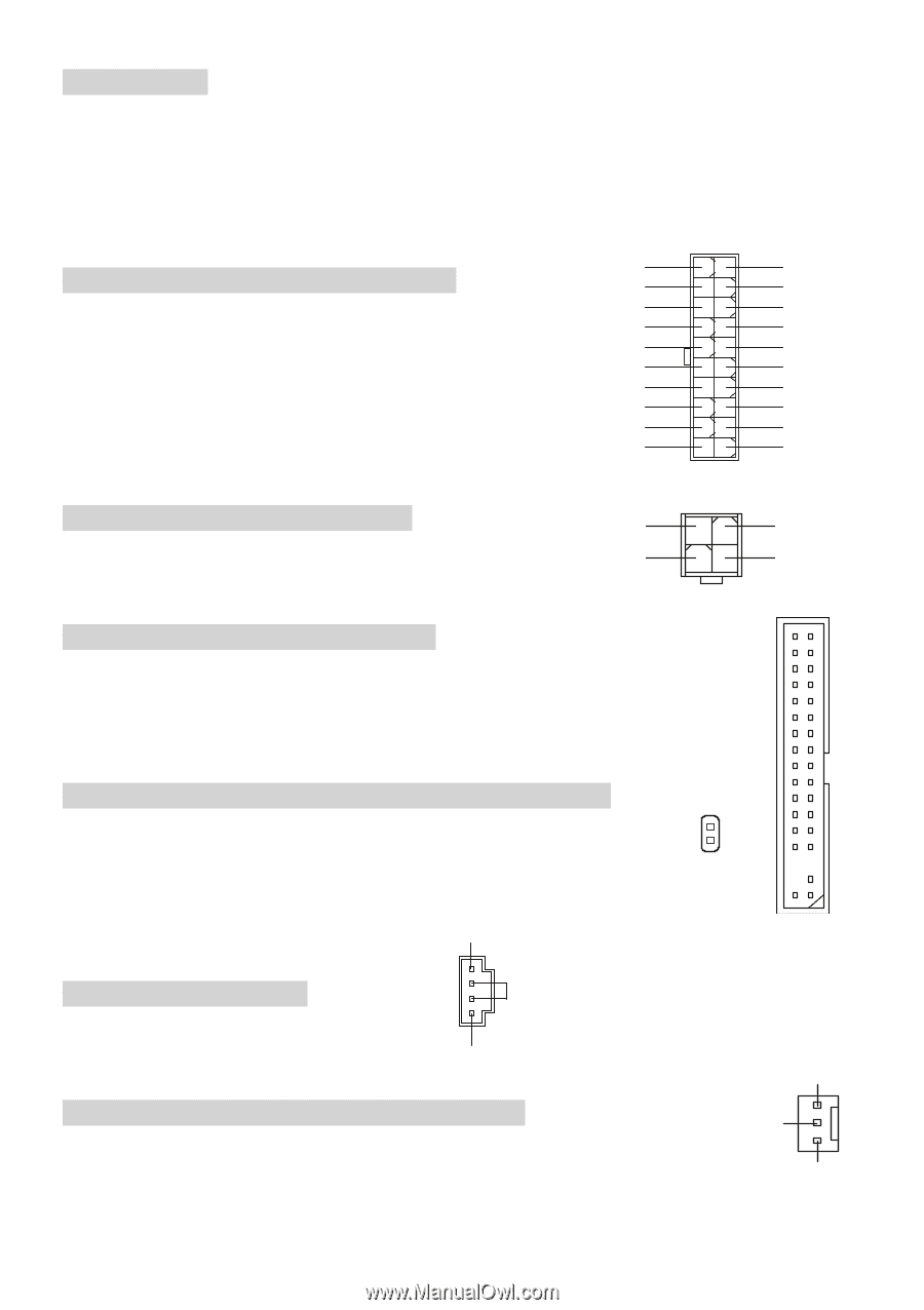
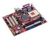
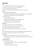
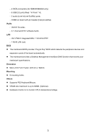
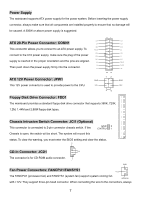
Power Supply The mainboard supports ATX power supply for the power system. Before inserting the power supply connector, always make sure that all components are installed properly to ensure that no damage will be caused. A 300W or above power supply is suggested. 3.3V ATX 20-Pin Power Connector: CONN1 -12V GND This connector allows you to connect to an ATX power supply. To PS_ON GND connect to the ATX power supply, make sure the plug of the power GND GND supply is inserted in the proper orientation and the pins are aligned. -5V 5V Then push down the power supply firmly into the connector. 5V ATX 12V Power Connector: JPW1 GND This 12V power connector is used to provide power to the CPU. 12V 11 1 20 10 12 34 3.3V 3.3V GND 5V GND 5V GND PW_OK 5V_SB 12V GND 12V Floppy Disk Drive Connector: FDD1 The mainboard provides a standard floppy disk drive connector that supports 360K, 720K, 1.2M, 1.44M and 2.88M floppy disk types. Chassis Intrusion Switch Connector: JCI1 (Optional) This connector is connected to 2-pin connector chassis switch. If the GND 2 CINTRU 1 Chassis is open, the switch will be short. The system will record this status. To clear the warning, you must enter the BIOS setting and clear the status. R CD-In Connector: JCD1 GND The connector is for CD-ROM audio connector. L GND Fan Power Connectors: FANCPU1/FANSYS1 +12V The FANCPU1 (processor fan) and FANSYS1 (system fan) support system cooling fan SENSOR with +12V. They support three-pin head connector. When connecting the wire to the connectors, always 7
-
 1
1 -
2
-
3
-
4
-
5
-
 6
6 -
 7
7 -
 8
8 -
 9
9 -
 10
10 -
 11
11 -
 12
12 -
 13
13 -
 14
14 -
 15
15 -
 16
16 -
17
-
18
-
19
-
20
-
21
-
22
-
23
-
24
-
25
-
26
-
27
-
28
-
29
-
30
-
31
-
32
-
33
-
34
-
35
-
36
-
37
-
38
-
39
-
40
-
41
-
42
-
43
-
44
-
45
-
46
-
47
-
48
-
49
-
50
-
51
-
52
-
53
-
54
-
55
-
56
-
57
-
58
-
59
-
60
-
61
-
62
-
63
-
64
-
65
-
66
-
67
-
68
-
69
-
70
-
71
-
72
-
73
-
74
-
75
-
76
-
77
-
78
-
79
-
80
-
81
-
82
-
83
-
84
-
85
-
86
-
87
-
88
-
89
-
90
-
91
-
92
-
93
-
94
-
95
-
96
-
97
-
98
-
99
-
100
-
101
-
102
 |
 |