MSI KM4M-V User Guide - Page 9
Memory Speed/CPU FSB Support Matrix, CPU Installation Procedures for Socket 462, Installing the CPU
 |
UPC - 816909005301
View all MSI KM4M-V manuals
Add to My Manuals
Save this manual to your list of manuals |
Page 9 highlights
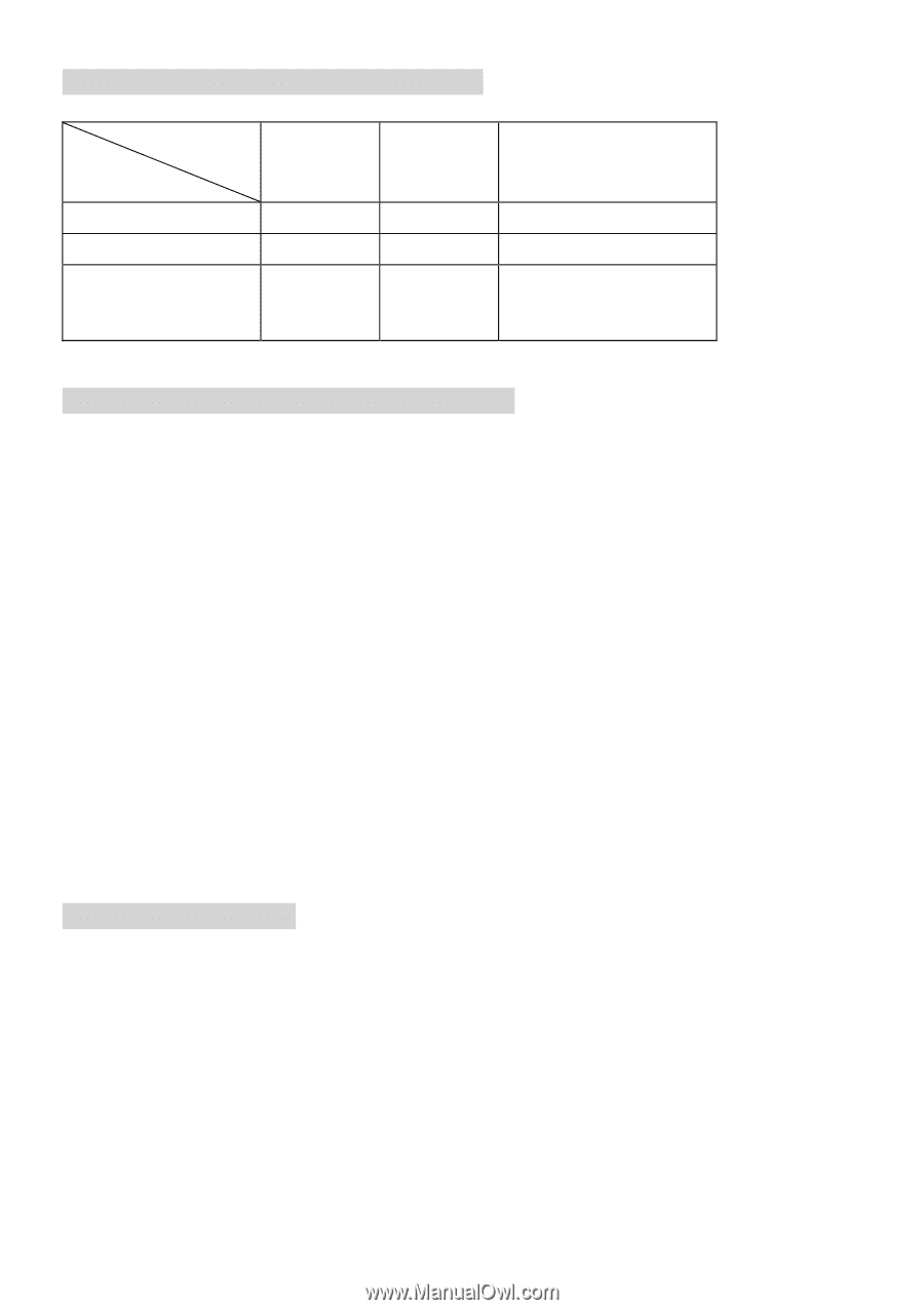
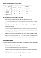
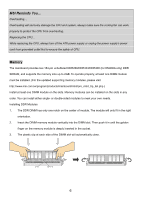
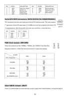
Memory Speed/CPU FSB Support Matrix Memory FSB 266 MHz 333 MHz 400 MHz (For KM400A only) DDR 266 OK OK OK DDR 333 OK OK OK DDR 400 (For KM400A only) OK OK OK CPU Installation Procedures for Socket 462 1. Please turn off the power and unplug the power cord before installing the CPU. 2. Pull the lever sideways away from the socket. Make sure to raise the lever up to a 90-degree angle. 3. Look for the gold arrow. The gold arrow should point towards the lever pivot. The CPU can only fit in the correct orientation. 4. If the CPU is correctly installed, the pins should be completely embedded into the socket and can not be seen. Please note that any violation of the correct installation procedures may cause permanent damages to your mainboard. 5. Press the CPU down firmly into the socket and close the lever. As the CPU is likely to move while the lever is being closed, always close the lever with your fingers pressing tightly on top of the CPU to make sure the CPU is properly and completely embedded into the socket. Installing the CPU Fan The following instructions will guide you through the heat sink installation procedures. Please consult your agent for the proper CPU cooler set. 1. Position your CPU cooler set onto the CPU. 2. Use one end of the clip to hook the latch of the CPU sliding plate. 3. Hook the other latch to fix the cooling fan set. You may need a screw drive to press down the other side of the clip. 4. Connect the fan to the power supply connector provided on your mainboard. 5
-
 1
1 -
2
-
3
-
 4
4 -
 5
5 -
 6
6 -
 7
7 -
 8
8 -
 9
9 -
 10
10 -
 11
11 -
 12
12 -
 13
13 -
 14
14 -
15
-
16
-
17
-
18
-
19
-
20
-
21
-
22
-
23
-
24
-
25
-
26
-
27
-
28
-
29
-
30
-
31
-
32
-
33
-
34
-
35
-
36
-
37
-
38
-
39
-
40
-
41
-
42
-
43
-
44
-
45
-
46
-
47
-
48
-
49
-
50
-
51
-
52
-
53
-
54
-
55
-
56
-
57
-
58
-
59
-
60
-
61
-
62
-
63
-
64
-
65
-
66
-
67
-
68
-
69
-
70
-
71
-
72
-
73
-
74
-
75
-
76
-
77
-
78
-
79
-
80
-
81
-
82
-
83
-
84
-
85
-
86
-
87
-
88
-
89
-
90
-
91
-
92
-
93
-
94
-
95
-
96
-
97
-
98
-
99
-
100
-
101
-
102
 |
 |