MSI KT880 User Guide - Page 24
Back Panel, Keyboard Connector in purple, Mouse Connector in green, USB 2.0 Connectors
 |
UPC - 816909006063
View all MSI KT880 manuals
Add to My Manuals
Save this manual to your list of manuals |
Page 24 highlights
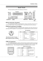
Hardware Setup Back Panel The back panel provides the following connectors: Mouse Parallel L-in SPDIF Out LAN Keyboard COMA USB Ports USB Ports L-out MIC Mouse Connector (in green) The mainboard provides a standard PS/2® mouse mini DIN connector for attaching a PS/2® mouse. You can plug a PS/2® mouse directly into this connector. Keyboard Connector (in purple) The mainboard provides a standard PS/2® keyboard mini DIN connector for attaching a PS/2® keyboard. You can plug a PS/2® keyboard directly into this connector. 6 5 PIN 4 3 1 2 2 1 3 PS/2 Mouse (6-pin Female) 4 5 PS/2 Keyboard (6-pin Female) 6 Pin Definition SIGNAL Mouse DATA (or Keyboard DATA) NC GND VCC Mouse Clock (or Keyboard Clock) NC DESCRIPTION Mouse DATA (or Keyboard DATA) No connection Ground +5V Mouse clock (or Keyboard Clock) No connection USB 2.0 Connectors The mainboard provides a UHCI (Universal Host Controller Interface) Universal Serial Bus root for attaching USB devices such as keyboard, mouse or other USBcompatible devices. You can plug the USB device directly into the connector. USB Port Description 1 2 3 4 5 6 7 8 USB Ports PIN SIGNAL 1 VCC 2 -Data 0 3 +Data0 4 GND 5 VCC 6 -Data 1 7 +Data 1 8 GND DESCRIPTION +5V Negative Data Channel 0 Positive Data Channel 0 Ground +5V Negative Data Channel 1 Positive Data Channel 1 Ground 2-9
-
 1
1 -
2
-
3
-
4
-
5
-
6
-
7
-
8
-
9
-
10
-
11
-
12
-
13
-
14
-
15
-
16
-
17
-
18
-
 19
19 -
 20
20 -
 21
21 -
 22
22 -
 23
23 -
 24
24 -
 25
25 -
 26
26 -
 27
27 -
 28
28 -
 29
29 -
30
-
31
-
32
-
33
-
34
-
35
-
36
-
37
-
38
-
39
-
40
-
41
-
42
-
43
-
44
-
45
-
46
-
47
-
48
-
49
-
50
-
51
-
52
-
53
-
54
-
55
-
56
-
57
-
58
-
59
-
60
-
61
-
62
-
63
-
64
-
65
-
66
-
67
-
68
-
69
-
70
-
71
-
72
-
73
-
74
-
75
-
76
-
77
-
78
-
79
-
80
-
81
-
82
-
83
-
84
-
85
-
86
-
87
-
88
-
89
-
90
-
91
-
92
-
93
-
94
-
95
-
96
-
97
-
98
-
99
-
100
-
101
-
102
-
103
-
104
-
105
 |
 |
