MSI P965 NEO-F User Guide - Page 30
Chassis Intrusion Switch Connector: JCASE1, Fan Power Connectors: CPUFAN1, NBFAN1, SYSFAN1 - chipset mainboard
 |
UPC - 816909035490
View all MSI P965 NEO-F manuals
Add to My Manuals
Save this manual to your list of manuals |
Page 30 highlights
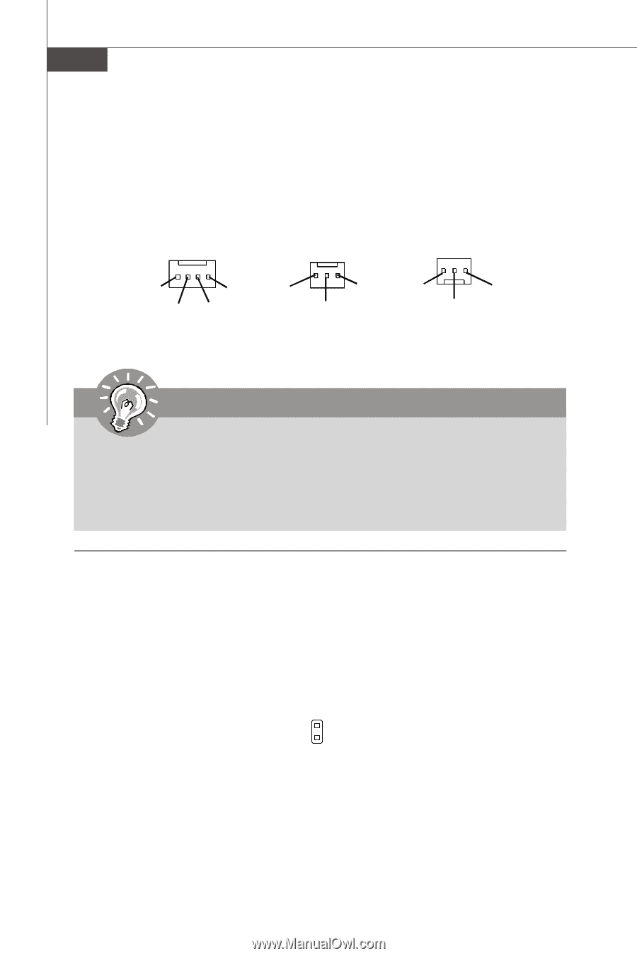
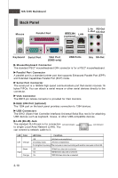
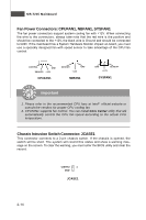
MS-7235 Mainboard Fan Power Connectors: CPUFAN1, NBFAN1, SYSFAN1 The fan power connectors support system cooling fan with +12V. W hen connecting the wire to the connectors, always take note that the red wire is the positive and should be connected to the +12V, the black wire is Ground and should be connected to GND. If the mainboard has a System Hardware Monitor chipset on-board, you must use a specially designed fan with speed sensor to take advantage of the CPU fan c on tr ol . CONTROL GND SENSOR +1 2V CPUFAN1 SE NS OR +1 2V GND NBFAN1 GND SE NS OR +1 2V SYSFAN1 Important 1. Please refer to the recommended CPU fans at Intel® official website or consult the vendors for proper CPU cooling fan. 2. CPUFAN1 supports fan control. You can install Core Center utility that will automatically control the CPU fan speed according to the actual CPU temperature. Chassis Intrusion Switch Connector: JCASE1 This connector connects to a 2-pin chassis switch. If the chassis is opened, the switch will be short. The system will record this status and show a warning message on the screen. To clear the warning, you must enter the BIOS utility and clear the record. CINTRU 1 GND JCASE1 2-14
-
 1
1 -
2
-
3
-
4
-
5
-
6
-
7
-
8
-
9
-
10
-
11
-
12
-
13
-
14
-
15
-
16
-
17
-
18
-
19
-
20
-
21
-
22
-
23
-
24
-
 25
25 -
 26
26 -
 27
27 -
 28
28 -
 29
29 -
 30
30 -
 31
31 -
 32
32 -
 33
33 -
 34
34 -
 35
35 -
36
-
37
-
38
-
39
-
40
-
41
-
42
-
43
-
44
-
45
-
46
-
47
-
48
-
49
-
50
-
51
-
52
-
53
-
54
-
55
-
56
-
57
-
58
-
59
-
60
-
61
-
62
-
63
-
64
-
65
-
66
-
67
-
68
-
69
-
70
-
71
-
72
-
73
-
74
-
75
-
76
-
77
-
78
-
79
-
80
-
81
-
82
-
83
 |
 |