MSI PM8M3-V User Guide
MSI PM8M3-V - Motherboard - Micro ATX Manual
 |
UPC - 816909014624
View all MSI PM8M3-V manuals
Add to My Manuals
Save this manual to your list of manuals |
MSI PM8M3-V manual content summary:
- MSI PM8M3-V | User Guide - Page 1
if not installed and used in accordance with the instruction manual, may cause harmful interference to radio communications. However, VOIR LA NOTICE D'NSTALLATION AVANT DE RACCORDER AU RESEAU. Micro-Star International MS-7211 This device complies with Part 15 of the FCC Rules. Operation is subject - MSI PM8M3-V | User Guide - Page 2
Microsoft® is a registered trademark of Microsoft Corporation. Windows® 98/2000/NT/XP are registered trademarks of Microsoft Corporation. NVIDIA, the and CardBus are registered trademarks of the Personal Computer Memory Card International Association. Revision History Revision Revision History - MSI PM8M3-V | User Guide - Page 3
1. Always read the safety instructions carefully. 2. Keep this User Manual for future reference. 3. Keep this equipment away shock. 11. If any of the following situations arises, get the equipment checked by a service personnel: - The power cord or plug is damaged. - Liquid has penetrated into the - MSI PM8M3-V | User Guide - Page 4
sein de la communauté européenne. Par conséquent vous pouvez retourner localement ces matériels dans les points de collecte. MSI WEEE 2002/96/EC 13 2005 MSI MSI EC Español MSI como empresa comprometida con la protección del medio ambiente, recomienda: Bajo la directiva 2002/96/EC de la Uni - MSI PM8M3-V | User Guide - Page 5
Tyto výrobky můžete odevzdat v místních sběrnách. MAGYAR Annak érdekében, hogy környezetünket megvédjük, illetve környezetvédőként fellépve az MSI emlékezteti Önt, hogy ... Az Európai Unió („EU") 2005. augusztus 13-án hatályba lépő, az elektromos és elektronikus berendezések hulladékairól szóló 2002 - MSI PM8M3-V | User Guide - Page 6
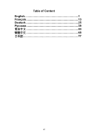
Table of Content English 1 Français 13 Deutsch 25 39 53 65 77 vi - MSI PM8M3-V | User Guide - Page 7
Thank you for choosing the PM8M3-V (MS-7211 v1.x) Micro-ATX mainboard. The PM8M3-V is design based on VIA® P4M800 & VIA® VT8237R Plus chipsets for optimal system efficiency. Designed for the Intel® P4 processors supporting Hyper-Threading Technology in the LGA775 package, the PM8M3-V delivers a high - MSI PM8M3-V | User Guide - Page 8
://www.msi.com.tw/program/products/mainboard/mbd/pro_mbd_cpu_support.php ) Chipset • VIA® P4M800CE chipset - P4 processors FSB (800MHz). - DDR SDRAM memory (333/400MHz). - AGP 8x. - Supports 8X V-Link. • VIA® VT8237R plus chipset - Integrated Hardware Sound Blaster/Direct Sound AC97 audio - Ultra - MSI PM8M3-V | User Guide - Page 9
serial port (COM1) - 1 parallel port supports SPP/EPP/ECP mode - 8 USB 2.0 ports (Rear * 4/ Front * 4) - 1 audio (Line-In/Line-Out/Mic) port - 1 RJ45 LAN jack - 1 VGA port - 1 COM2 pin header - 2 SATA 150 BIOS • The mainboard BIOS provides "Plug & Play" BIOS which detects the peripheral devices and - MSI PM8M3-V | User Guide - Page 10
In Line Out Mic In Keyboard COM port VGA port USB Ports Hardware Setup This chapter tells you how to install the CPU, memory modules, and expansion cards, as well as how to setup the jumpers on the mainboard. It also provides the instructions on connecting the peripheral devices, such as the - MSI PM8M3-V | User Guide - Page 11
. The pins of socket reveal. 7. Lift the load lever up and open the load plate. 8. Correctly align the triangle of CPU Clip with the CPU chamfer, and the square on the CPU Clip to the hook of the socket. 9. Use your thumb and the middle fingers to push the clips to release the - MSI PM8M3-V | User Guide - Page 12
/unplug the CPU too often. Memory The mainboard provides two 184-pin unbuffered DDR333 / DDR400 DDR SDRAM, and supports the memory size up to 2GB. To operate properly, at least one DIMM module must be installed. (For the updated supporting memory modules, please visit http://www.msi.com.tw/program - MSI PM8M3-V | User Guide - Page 13
to provide power to the CPU. 12V Floppy Disk Drive Connector: FDD1 The mainboard provides a standard floppy disk drive connector that supports 360K, 720K, 1.2M, by hard disk vendors for jumper setting instructions. Serial ATA Connectors controlled by VIA® 8237R Plus: SATA1/SATA2 The mainboard - MSI PM8M3-V | User Guide - Page 14
block area can be updated. When locked, the BIOS boot block area cannot be updated. 2 2 1 1 BIOS Flash Unlocked BIOS Flash Locked Fan Power Connectors: CPUFAN1/SYSFAN1/PWRFAN1 The 4-pin CPUFAN1 (processor fan) and 3-pin SYSFAN1 (system fan)/PWRFAN1 (power fan) support system cooling fan with - MSI PM8M3-V | User Guide - Page 15
USB 1.1, and is ideal for connecting high-speed USB interface peripherals such as USB HDD, digital cameras, MP3 players, printers, modems, etc. MSI instructions in the image to clear the data. MSI memory. The slot supports AGP card for 8x/4x at 1.5v (3.3v is not supported BIOS configuration. 9 - MSI PM8M3-V | User Guide - Page 16
for basic system configurations, such as time, date etc. Advanced BIOS Features Use this menu to setup the items of Award special enhanced features. Advanced Chipset Features Use this menu to change the values in the chipset registers and optimize your system performance. Integrated Peripherals Use - MSI PM8M3-V | User Guide - Page 17
BIOS setting Password. Save & Exit Setup Save changes to CMOS and exit setup. Exit Without Saving Abandon all changes and exit setup. Frequency/Voltage Current FSB Clock It shows the current FSB clock of . Read-only. Adjust CPU the motherboard's clock do not have any EMI problem, leave the setting at - MSI PM8M3-V | User Guide - Page 18
Frequency This item allows you to select the CPU/AGP/PCI Front Side Bus clock frequency (in MHz) and overclock the processor by adjusting the FSB clock to a higher frequency. Memory Voltage Adjusting the DDR voltage can increase the DDR speed. Any changes made to this setting may cause a stability - MSI PM8M3-V | User Guide - Page 19
venez d'acheter une carte micro ATX PM8M3-V (MS-7211 v1.x). la PM8M3-V est construite autour des chipsets VIA® P4M800 & VIA® VT8237R. Elle fonctionne avec des processeurs Intel® P4 supportant la technologie Hyper-Threading (LGA775 package). La PM8M3-v offre des performances tant aux particuliers - MSI PM8M3-V | User Guide - Page 20
les CPU supportés, veuillez visiter http://www.msi.com.tw/program/products/mainboard/mbd/pro_mbd_cpu_support.php ) Chipset • Chipset VIA® P4M800CE - Processeurs P4 FSB (800MHz) - Mémoire DDR SDRAM (333/400MHz) - AGP 8x - Supporte 8X V-Link. • Chipset VIA® VT8237R Plus - Matériel audio Sound Blaster - MSI PM8M3-V | User Guide - Page 21
- 1 port série (COM1) - 1 port parallèle supportant les modes SPP/EPP/ECP - 8 ports USB 2.0 (Arrière * 4/ Avant * 4) - 1 port audio (Line-In/Line-Out/Mic) - 1 jack RJ45 LAN - 1 port VGA - 1 jeu de broches COM2 - 2 SATA 150 BIOS • La carte offre un BIOS "Plug & Play" qui détecte automatiquement les - MSI PM8M3-V | User Guide - Page 22
Keyboard COM port VGA port USB Ports Installation Matériel Ce chapitre vous indique comment installer le CPU, mémoire, et cartes d'extension, clavier, souris ... Lors de ces installations, merci de bien suivre les procédures.. Central Processing Unit: CPU La carte supporte les processeurs Intel - MSI PM8M3-V | User Guide - Page 23
trouve sur le socket de la carte mère. Veuillez ne pas toucher aux broches du socket. 4. Aligner les indicateurs de couleur jaune (triangle sur le CPU & sur le clip), et utiliser le clip MSI pour fixer le processeur sur le socket en pratiquant de la façon indiquée sur la photo. 5. Le - MSI PM8M3-V | User Guide - Page 24
MSI Vous Rappelle ... 1. Vérifier la connexion du ventilateur de CPU avant de démarre le PC. 2. Vérifier les informations dans le BIOS PC Health Status du H/W Monitor au sujet de la température du CPU. 3. Ne pas toucher les broches du CPU pour éviter de les endommager. 4. Le CPU possède un capot - MSI PM8M3-V | User Guide - Page 25
CPU. 12V Connecteur Floppy Disk Drive: FDD1 La carte offre un connecteur standard floppy disk drive (lecteur de disquette) qui supporte disque dur pour les instructions. Connecteurs Serial ATA contrôlés par VIA® 8237R Plus: SATA1 disque dur. MSI Vous Rappelle... Ne pas tordre le câble Sata à 90° - MSI PM8M3-V | User Guide - Page 26
ler le ventilateur du CPU MSI Vous Rappelle... Toujours consulter votre revendeur au sujet du ventilateur de CPU. Connecteurs Front Panel : le signal vers les ports audio à l'arrière. Autrement le connecteur Line-Out à l'arrière ne fonctionnera pas. 21 Connecteur Front USB : JUSB1/JUSB2 USB0+ - MSI PM8M3-V | User Guide - Page 27
ées. Suivez les instructions de l'image pour effacer les données. MSI Vous Rappelle... Vous pouvez principale. Le slot supporte les cartes AGP 8x/4x en 1.5v (le 3.3v n'est pas supporté). Slots PCI PCI pour les différents réglages (cavalier, BIOS ...). PCI Interrupt Request Routing IRQ est l'abré - MSI PM8M3-V | User Guide - Page 28
BIOS BIOS. Advanced BIOS Features Cette fonction permet de paramétrer des éléments avancés du Bios. Advanced Chipset Features Cette option vous permet de paramétrer les éléments relatifs au registre du chipset supporte PNP/PCI. H/W Monitor Cette entrée montre le statut de votre - MSI PM8M3-V | User Guide - Page 29
de passe BIOS Save & Exit Setup Sauvegarder les changements du CMOS et sortir de l'utilitaire de Setup. Exit Without Saving Abandonner tous les changements et sortir de l'utilitaire de Setup. Fréquence/Voltage Current FSB Clock Montre le FSB actuel. Lecture uniquement. Adjust CPU Ratio Cet élément - MSI PM8M3-V | User Guide - Page 30
En ajustant le voltage DDR, vous pouvez augmenter la vitesse DDR. Tout changement effectué sur cette option peut entraîner une instabilité, donc changer le voltage DDR à long terme n'est pas recommandé. AGP Voltage Le voltage AGP est ajustable et permet d'augmenter la performance de la carte d' - MSI PM8M3-V | User Guide - Page 31
Sie das PM8M3-V (MS-7211 v1.x) Micro- ATX Mainboard gewählt haben. Das PM8M3-V basiert auf den VIA® P4M800 und VIA® VT8237R Plus PM8M3-V die ideale Lösung zum Aufbau eines professionellen Hochleistungsdesktopsystems dar. Layout Oben: Maus Unten: Tastatur Oben: Parallel Port Unten: COM 1 VGA Port USB - MSI PM8M3-V | User Guide - Page 32
://www.msi.com.tw/program/products/mainboard/mbd/pro_mbd_cpu_support.php) Chipsatz • VIA® P4M800CE Chipsatz - P4 Prozessor FSB (800MHz). - DDR SDRAM Speicher (333/400MHz). - AGP 8x. - Unterstützt 8X V-Link. • VIA® VT8237R Plus Chipsatz - Integrierte Hardware Sound Blaster/Direct Sound AC97 Audiol - MSI PM8M3-V | User Guide - Page 33
Audio • In den VT8237R Plus integrierter AC97 Anschlusskontroller. • Realtek® ALC655 6-Kanal USB 2.0 Ports (4 hintere/ 4 vordere) - 1 Set Audioanschlüsse (Line-In/Line-Out/Mic) - 1 RJ45 LAN Buchse - 1 VGA Port - 1 COM2 Anschluss ausgeführt als Stiftleiste - 2 SATA 150 BIOS z Das Mainboard- BIOS - MSI PM8M3-V | User Guide - Page 34
/mainboard/mbd/pro_mbd_cpu_support.php MSI weist darauf hin... Überhitzung Überhitzung beschädigt die CPU und das System nachhaltig, stellen Sie stets eine korrekte Funktionsweise des CPU Kühlers sicher, um die CPU vor Überhitzung zu schützen. Übertakten Dieses Motherboard wurde so entworfen, dass - MSI PM8M3-V | User Guide - Page 35
Bitte achten Sie darauf, die Kontakte nicht zu berühren. 4. Richten Sie die zwei Markierungen am Pin 1 aus (die Dreiecke auf CPU und CPU Clip), und verwenden Sie den CPU Clip, um die CPU aufzunehmen, indem Sie die Klammern an beiden Seiten zur Mitte hin drücken, wie die Pfeile es anzeigen. 5. Um die - MSI PM8M3-V | User Guide - Page 36
Sie den Clip auf, um die CPU herauszuheben. MSI weist darauf hin... 1. Stellen Sie den festen Sitz Ihres CPU- Kühlers sicher, bevor Sie das System anschalten. 2. Überprüfen Sie die Temperatur der CPU im "PC Health Status" der Hardwareüberwachung (H/W Monitor) im BIOS. 3. Um Schäden zu vermeiden, ber - MSI PM8M3-V | User Guide - Page 37
: JPW1 Dieser 12V Stromanschluss wird verwendet, um die CPU mit 12V Strom zu versorgen. 12V Anschluss des Diskettenlaufwerks einer Steckbrücke als Slave eingestellt werden. MSI weist darauf hin... Verbinden Sie zwei Laufwerke Anschlüsse gesteuert durch den VIA® 8237R SATA1/SATA2 Dieses - MSI PM8M3-V | User Guide - Page 38
MSI CINTRO BIOS Flash Jumper: JWP1 Diese Steckbrücke dient dazu, um den Bootbereich des BIOS zu BIOS aktualisiert werden. Ist er gesperrt, kann der Bootbereich des BIOS nicht aktualisiert werden. 2 1 BIOS Flash entsperrt 2 1 BIOS zu nutzen. MSI weist darauf hin... Bitten Sie stets Ihren Hä - MSI PM8M3-V | User Guide - Page 39
AUD_FPOUT_L HP_ON Der Audio Vorderanschluss ermöglicht Intel® Front 21 Panel I/O Connectivity Design Guide". MSI weist darauf hin... 10 9 Wenn Sie USB Vorderanschluss: JUSB1/JUSB2 Das Mainboard verfügt über zwei Standard- USB- 2.0Anschlüsse in Form der Stift- Blöcke JUSB1 und JUSB2. Die USB - MSI PM8M3-V | User Guide - Page 40
CMOS Löschung). Befolgen Sie die Anweisungen in der Grafik, um die Daten zu löschen. MSI weist darauf hin... Sie können den CMOS löschen, indem Sie die Pins 2-3 verbinden, sei es an Steckbrücken ("Jumpern"), Schaltern oder im BIOS. PCI Interrupt Request Routing Die IRQs (Interrupt Request Lines) - MSI PM8M3-V | User Guide - Page 41
Basiskonfiguration Ihres Systems anpassen, so z.B. Uhrzeit, Datum usw. Advanced BIOS Features Verwenden Sie diesen Menüpunkt, um Award- eigne weitergehende Monitor Dieser Eintrag zeigt den Status der CPU, des Lüfters und allgemeine Warnungen zum generellen Systemstatus. Frequency/Voltage Control 35 - MSI PM8M3-V | User Guide - Page 42
BIOS.. Exit Without Saving Verlassen des BIOS´ ohne Speicherung, vorgenommene Änderungen verfallen. Frequency/Voltage Current FSB Clock Gibt den derzeitigen Takt des FSB wieder. Nur Anzeige. Adjust CPU Ratio Hier können Sie die CPU des Motherboards, erzeugen für sie EMI ein Problem dar, wählen Sie - MSI PM8M3-V | User Guide - Page 43
AGP/PCI Frequency Gestattet es, die Taktfrequenz des CPU/AGP/PCI Front Side Bus (in MHz) zu wählen und den Prozessor zu übertakten, indem der FSB Takt hoch gesetzt wird. Memory Voltage Die Spannung des DDR anzuheben, kann diesen beschleunigen. Jede Änderung dieser Option kann zu Stabilitätsproblemen - MSI PM8M3-V | User Guide - Page 44
Load Optimized Defaults Hier können Sie die BIOS- Voreinstellungen für den stabilen Betrieb laden, die der Mainboardhersteller vorgibt. 38 - MSI PM8M3-V | User Guide - Page 45
PM8M3-V (MS-7211 v1.x) Micro-ATX PM8M3-V VIA® P4M800 и VIA® VT8237R Plus LGA775 Intel® P4 Hyper-Threading, PM8M3-V 39 - MSI PM8M3-V | User Guide - Page 46
P4 Prescott 3.2ГГц и Intel P4 Prescott Celeron http://www.msi.com.tw/program/products/mainboard/mbd/pro_mbd_cpu_support.php ) VIA® P4M800CE P4 FSB (800 DDR SDRAM (333/400 AGP 8x 8X V-Link. • VIA® VT8237R plus Sound Blaster/Direct Sound AC97. - Ultra DMA 66/100/133 PCI EIDE bus master - MSI PM8M3-V | User Guide - Page 47
PCI 2.2 ACPI. - 1 floppy 2 FDD с 360K, 720K, 1.2M, 1.44M и 2.88МБ - 1 COM1) - 1 SPP/EPP/ECP - 8 USB 2.0 (4 4 1 Line-In/Line-Out/Mic) - 1 RJ45 - 1 VGA порт - 1 COM2 - 2 SATA 150 BIOS • BIOS Plug & Play" BIOS Desktop Management Interface (DMI Micro-ATX 245мм x 210 6 41 - MSI PM8M3-V | User Guide - Page 48
Intel® Pentium 4 LGA775 http://www.msi.com.tw/program/products/mainboard/mbd/pro_mbd_cpu_support.php. MSI FSB FSB 533 МГц 800 МГц DDR 333 OK OK DDR 400 OK OK 42 - MSI PM8M3-V | User Guide - Page 49
LGA775 CPU Clip 1 1 2 CPU Clip 1 3 4 1 CPU Clip CPU Clip 5 6 7 8 CPU Clip с 9 10 11 CPU Clip 12 13 43 - MSI PM8M3-V | User Guide - Page 50
14 15 CPU Clip 8 MSI 1 2 BIOS'a "PC Health Status H/W Monitor 3 4 5 20 Память 184 DDR333 / DDR400 DDR SDRAM 2 DIMM http://www.msi.com.tw/program/products/mainboard/mbd/pro_mbd_trp_list.php DIMM DDR Выступ Ключ 1 DDR DIMM 44 - MSI PM8M3-V | User Guide - Page 51
: IDE1/IDE2 Ultra DMA 66/100/133 PIO mode 0~4, Bus Master, и Ultra DMA 66/100/133 CD-ROM, 120 IDE IDE1. IDE1 Master и Slave Slave MSI Slave 45 - MSI PM8M3-V | User Guide - Page 52
ATA VIA® 8237R Plus: SATA1/SATA2 Serial ATA 1 Serial ATA 150 Serial ATA 1.0 Serial ATA 1 MSI 90 Serial ATA CD-In: CD_IN1 R CDROM. GND L AUX In: AUX_IN1 L GND R aux-in). JC1 2 1 GND CINTRO BIOS'a: JWP1 BIOS BIOS 2 1 BIOS BIOS 2 1 BIOS - MSI PM8M3-V | User Guide - Page 53
JAUDIO1 JAUDIO1 Intel® Front Panel I/O Connectivity Design Guide. AUD_RET_L Key AUD_RET_R AUD_VCC AUD_GND 10 9 21 AUD_FPOUT_L HP_ON AUD_FPOUT_R AUD_MIC_BIAS AUD_MIC MSI 10 9 5 и 6, 9 и 10 Line-Out 2 1 USB JUSB1/JUSB2 USB 2.0 - JUSB1 и JUSB2 USB2.0 (9)Key (10)USB0C - MSI PM8M3-V | User Guide - Page 54
GND RTS RI 2 4 6 8 10 SIN DTR DSR CTS X X CMOS JBAT2 CMOS 1 2 3 CMOS 1 2 3 Keep Data 1 2 3 Clear Data CMOS JBAT2 CMOS MSI 2-3 CMOS 1 и 2 CMOS AGP (Accelerated Graphics Port) AGP AGP AGP 3D 66МГц, 32 8х/4x AGP 1.5В (AGP - MSI PM8M3-V | User Guide - Page 55
DEL>. DEL: Setup F11: Boot Menu TAB: Logo , и . Standard CMOS Features Advanced BIOS Features Advanced Chipset Features Integrated Peripherals Power Management Setup PNP/PCI Configurations PnP/PCI. H/W Monitor Frequency/Voltage Control 49 - MSI PM8M3-V | User Guide - Page 56
AGP Load Optimized Defaults BIOS BIOS Setting Password Save & Exit Setup CMOS). Exit Without Saving Frequency/Voltage Control Current FSB Frequency Adjust CPU Ratio CPU ratio 8] до [50]. Auto Detect DIMM/PCI Clock DIMM PCI DIMM) и PCI Enabled PCI EMI). Spread Spectrum EMI ( - MSI PM8M3-V | User Guide - Page 57
Enable Spread Spectrum Adjust CPU/AGP/PCI Frequency AGP/PCI FSB AGP/ PCI FSB Memory Voltage DDR DDR AGP Voltage AGP AGP AGP 1.5В до 1.8 0.05В. 51 - MSI PM8M3-V | User Guide - Page 58
Load Optimized Defaults BIOS BIOS'a 52 - MSI PM8M3-V | User Guide - Page 59
简介 PM8M3-V(MS-7211 v1.x)Micro-ATX 主板。PM8M3-V 是基于 VIA® P4M800 & VIA® VT8237R Plus Hyper-Threading LGA775 Intel® P4 PM8M3-V 布局 53 - MSI PM8M3-V | User Guide - Page 60
3.2GHz,支持 Intel P4 Prescott Celeron CPU CPU http://www.msi.com.tw/program/products/mainboard/mbd/pro_mbd_cpu_support.php ) VIA® P4M800CE 芯片组 - P4 处理器 FSB(800MHz) - DDR SDRAM 内存(333/400MHz) - AGP 8x - 支持 8X V-Link • VIA® VT8237R plus Hardware Sound Blaster/Direct Sound AC97 音频 - Ultra DMA 66/100 - MSI PM8M3-V | User Guide - Page 61
仅对于 8110SB PCI 2.2 ACPI - 1 2 台 360K, 720K, 1.2M, 1.44M 和 2.88 Mbytes 1 COM1) - 1 SPP/EPP/ECP 模式 - 8 个 USB 2.0 4/ 前置* 4) - 1 Line-In/Line-Out/Mic)端口 - 1 个 RJ45 LAN 插孔 - 1 个 VGA 端口 - 1 个 COM2 针头 - 2 个 SATA 150 接口 BIOS BIOS 提供"Plug & Play DMI 尺寸 • Micro-ATX 245mm x 210mm 6 55 - MSI PM8M3-V | User Guide - Page 62
Line In Line Out Mic In Keyboard COM port VGA port USB Ports 硬件安装 CPU CPU LGA775 封装的 Intel ® Pentium 4 LGA775 封装的 CPU CPU CPU CPU CPU CPU http://www.msi.com.tw/program/products/mainboard/mbd/pro_mbd_cpu_support.php. CPU CPU CPU FSB 内存 FSB 533 MHz 800 MHz DDR 333 OK - MSI PM8M3-V | User Guide - Page 63
LGA775 CPU CPU 当您安装CPU CPU CPU CPU CPU CPU CPU 1. CPU CPU CPU 1 CPU 2 CPU CPU 1 3 CPU 4 1 CPU 和 CPU CPU CPU 5. CPU CPU CPU 6 7 8. 对齐 CPU CPU CPU 9 CPU CPU CPU 10. CPU 11 CPU CPU 12 13 4 14. 把 4 15 CPU 4 8 CPU 1 CPU 2. 请在 BIOS - MSI PM8M3-V | User Guide - Page 64
http://www.msi.com.tw/program/products/mainboard/mbd/pro_mbd_trp_list.php DDR 内存 Volt +3.3V 1 13 GND +5V +5V +5V Res GND GND GND PS-ON# GND -12V +3.3V ATX 12V JPW1 12V 此 12V CPU 供电。 12V FDD1 1 FDD1,支持 360K, 720K, 1.2M, 1.44M 和 2.88M 42 31 GND GND IDE 接口:IDE1/IDE2 主板有 2 个 - MSI PM8M3-V | User Guide - Page 65
跳线:JWP1 BIOS BIOS BIOS 2 2 1 1 BIOS Flash Unlocked BIOS Flash Locked CPUFAN1/SYSFAN1/PWRFAN1 此 4-pin 的 CPUFAN1 3-pin 的 SYSFAN1 PWRFAN1 12V 3-pin 或 4-pin 12V, Control Sensor +12V GND CPU_FAN1 Sensor +12V GND SY S _ FAN 1/ PWR _FAN GND CPU JFP2 JFP2 是符合 Intel - MSI PM8M3-V | User Guide - Page 66
符合 Intel® I/O AUD_VCC AUD_GND HP_ON AUD_FPOUT_R AUD_MIC_BIAS AUD_MIC 21 10 9 5 & 6, 9 & 10 Line-Out 21 前置 USB 接口:JUSB1/JUSB2 2 个 USB2.0 的接口 JUSB1、JUSB2。USB 2.0 480Mbps,是 USB1.1 的 40 USB USB HDD MP3 (9)Key (10)USB0C USB0+ GND USB0- VCC(1) VCC(2) GND USB1USB1+ VCC - MSI PM8M3-V | User Guide - Page 67
PCI 总线的 INT A# ~ INTD# 引脚: Order1 Order2 Order3 Order4 PCI Slot 1 INT B# INT C# INT D# INT A# PCI Slot 2 INT C# INT D# INT A# INT B# BIOS 设置 POST DEL>键 DEL: Setup F11: Boot Menu TAB: Logo Setup Reset Ctrl>、和 - MSI PM8M3-V | User Guide - Page 68
PnP/PCI H/W Monitor PC CPU Frequency/Voltage Control Load Optimized Defaults BIOS 值。 BIOS Setting Password(BIOS BIOS Save & Exit Setup CMOS Setup 程序。 Exit Without Saving CMOS Setup 程序。 Current FSB Clock(当前 FSB FSB Adjust CPU Ratio(调整 CPU CPU 8]到[50]。 Auto Detect DIMM/PCI Clock - MSI PM8M3-V | User Guide - Page 69
Adjust CPU/AGP/PCI Frequency(调整 CPU/AGP/PCI CPU/AGP/PCI MHz FSB Memory Voltage DDR DDR DDR AGP Voltage(AGP 电压) AGP AGP 1.5V 至 1.85V,以 0.05V 63 - MSI PM8M3-V | User Guide - Page 70
64 - MSI PM8M3-V | User Guide - Page 71
簡介 PM8M3-V(MS-7211 v1.x)Micro-ATX PM8M3-V 是採用 VIA® P4M800 & VIA® VT8237R Plus Hyper-Threading LGA775 Intel® P4 PM8M3-V 配置圖 65 - MSI PM8M3-V | User Guide - Page 72
3.2GHz,支援 Intel P4 Prescott Celeron CPU CPU http://www.msi.com.tw/program/products/mainboard/mbd/pro_mbd_cpu_support.php ) VIA® P4M800CE 晶片組 - P4 處理器 FSB(800MHz) - DDR SDRAM 333/400MHz) - AGP 8x - 支援 8X V-Link • VIA® VT8237R plus Hardware Sound Blaster/Direct Sound AC97 音效 - Ultra DMA 66/100 - MSI PM8M3-V | User Guide - Page 73
僅對於 8110SB PCI 2.2 ACPI - 1 2 台 360K, 720K, 1.2M, 1.44M 和 2.88 Mbytes 1 COM1) - 1 SPP/EPP/ECP 模式 - 8 個 USB 2.0 4/ 前置* 4) - 1 Line-In/Line-Out/Mic)埠 - 1 個 RJ45 LAN 插孔 - 1 個 VGA 埠 - 1 個 COM2 針頭 - 2 個 SATA 150 介面 BIOS BIOS 提供"Plug & Play DMI 尺寸 • Micro-ATX 245mm x 210mm 6 67 - MSI PM8M3-V | User Guide - Page 74
Line In Line Out Mic In Keyboard COM port VGA port USB Ports 硬體安裝 CPU CPU LGA775 封裝的 Intel ® Pentium 4 LGA775 封裝的 CPU CPU CPU CPU CPU CPU http://www.msi.com.tw/program/products/mainboard/mbd/pro_mbd_cpu_support.php. CPU CPU CPU FSB 記憶體 FSB 533 MHz 800 MHz DDR 333 OK - MSI PM8M3-V | User Guide - Page 75
LGA775 CPU CPU 當您安裝CPU CPU CPU CPU CPU CPU CPU 1. CPU CPU CPU 1 CPU 2 CPU CPU 1 3 CPU 4 1 CPU 和 CPU CPU CPU 5. CPU CPU CPU 6 7 8. 對齊 CPU CPU CPU 9 CPU CPU CPU 10. CPU 11 CPU CPU 12 13 4 14. 把 4 15 CPU 4 8 CPU 1 CPU 2. 請在 BIOS - MSI PM8M3-V | User Guide - Page 76
http://www.msi.com.tw/program/products/mainboard/mbd/pro_mbd_trp_list.php DDR 記憶體 Volt Notch 3V GND +5V +5V +5V Res GND GND GND PS-ON# GND -12V +3.3V 1 13 ATX 12V JPW1 12V 此 12V CPU 供電。 12V FDD1 1 FDD1,支援 360K, 720K, 1.2M, 1.44M 和 2.88M 42 31 GND GND IDE 介面:IDE1/IDE2 2 個 32 - MSI PM8M3-V | User Guide - Page 77
跳線:JWP1 BIOS BIOS BIOS 2 2 1 1 BIOS Flash Unlocked BIOS Flash Locked CPUFAN1/SYSFAN1/PWRFAN1 此 4-pin 的 CPUFAN1 3-pin 的 SYSFAN1 PWRFAN1 12V 3-pin 或 4-pin 12V, Control Sensor +12V GND CPU_FAN1 Sensor +12V GND SY S _ FAN 1/ PWR _FAN GND CPU JFP2 JFP2 是符合 Intel - MSI PM8M3-V | User Guide - Page 78
符合 Intel® I/O AUD_VCC AUD_GND HP_ON AUD_FPOUT_R AUD_MIC_BIAS AUD_MIC 21 10 9 5 & 6, 9 & 10 Line-Out 21 前置 USB 介面:JUSB1/JUSB2 2 個 USB2.0 的介面 JUSB1、JUSB2。USB 2.0 480Mbps,是 USB1.1 的 40 USB USB HDD MP3 (9)Key (10)USB0C USB0+ GND USB0- VCC(1) VCC(2) GND USB1USB1+ VCC - MSI PM8M3-V | User Guide - Page 79
的 IRQ PCI INT A# ~ INTD# 引腳: Order1 Order2 Order3 Order4 PCI Slot 1 INT B# INT C# INT D# INT A# PCI Slot 2 INT C# INT D# INT A# INT B# BIOS 設定 POST DEL DEL: Setup F11: Boot Menu TAB: Logo Setup Reset Ctrl>、和 - MSI PM8M3-V | User Guide - Page 80
PnP/PCI H/W Monitor PC CPU Frequency/Voltage Control Load Optimized Defaults BIOS 值。 BIOS Setting Password(BIOS BIOS Save & Exit Setup CMOS Setup 程式。 Exit Without Saving CMOS Setup 程式。 Current FSB Clock(當前 FSB FSB Adjust CPU Ratio(調整 CPU CPU 8]到[50]。 Auto Detect DIMM/PCI Clock - MSI PM8M3-V | User Guide - Page 81
Adjust CPU/AGP/PCI Frequency(調整 CPU/AGP/PCI CPU/AGP/PCI MHz FSB Memory Voltage DDR DDR DDR AGP Voltage(AGP 電壓) AGP AGP 1.5V 至 1.85V,以 0.05V 75 - MSI PM8M3-V | User Guide - Page 82
76 - MSI PM8M3-V | User Guide - Page 83
Introduction PM8M3-V (MS-7211 v1.x) M-ATX VIA P4M800CE & VT8237R Plus Intel Pentium 4 Prescott / Celeron D MS-7211 v1.X CPU z LGA775 の Intel Pentium 4/Celeron D z FSB 周波数 800/533MHz、3.2GHz CPU http://www.msi.com.tw/program/products/mainboard/mbd/pro_mbd_cpu_support.php z VIA P4M800CE - - MSI PM8M3-V | User Guide - Page 84
PCI 2.2 32-bit PCI 2 (3.3v/5v PCI IDE - VIA VT8237R Plus IDE IDE HDD/CD-ROMに対してPIO Ultra DMA 33/66/100/133 - IDE 4 z - 1 360K, 720K, 1.2M, 1.44M, 2.88M FDD 1 COM 1) - 1 SPP/EPP/ECP 8 USB 2.0 ports x 4 x 4 ) - 1 1 RJ-45 LAN 1 VGA 1 COM 2 2 ATA 150MB/s) z VT8237R Plus AC'97 - MSI PM8M3-V | User Guide - Page 85
MS-7211 v1.X Micro-ATX Mainboard 79 - MSI PM8M3-V | User Guide - Page 86
COM port VGA port USB Ports Line In Line Out Mic In Hardware Setup Central Processing Unit: CPU Intel Pentium 4/ Celeron D LGA775 CPU CPU CPU http://www.msi.com.tw/program/products/mainboard/mbd/pro_mbd_cpu_support.php ) MSI Reminds You... CPU の過熱 CPU CPU CPU の交換 CPU ATX ATX - MSI PM8M3-V | User Guide - Page 87
CPU Memory FSB 533 MHz 800 MHz DDR 333 OK OK DDR 400 OK OK CPU & Cooler Installation 1. CPU CPU CPU の 1 CPU 2. CPU の 1 CPU CPU 4 CPU 3. CPU CPU CPU のピン(CPU CPU CPU 4 CPU CPU 5 CPU 2 6 CPU CPU CPU 7. CPU CPU CPU 8. 次に CPU CPU 9 81 - MSI PM8M3-V | User Guide - Page 88
Reminds You... 1 CPU CPU 2. BIOS の H/W Monitor PC Health Status にある CPU 3. CPU 4. CPU 5. CPU 20 1GB 184 2 DDR DIMM DDR333/DDR400 SDRAM 1 つの DIMM http://www.msi.com.tw/program/products/mainboard/mbd/pro_mbd_trp_list.php ) Volt Notch Installing DDR Modules 1. DDR DIMM - MSI PM8M3-V | User Guide - Page 89
ATX24 CONN1 ATX 電源 24 20 ピンの ATX 11/12/23/24 ATX 12V JPW1 この 12V CPU ます。 42 12V GND 12V GND 31 NC +12V +12V 5VSB PWR OK GND +5V GND +5V GND +3.3V DMA 66/100/133 4 CD-ROM 1 台目の HDD は通常 IDE1 IDE1 2 つ IDE/ATAPI 2 台目の HDD HDD IDE2 2 つ IDE/ATAPI MSI Reminds You 2 2 83 - MSI PM8M3-V | User Guide - Page 90
ATA 1.0 1 CD-In CD_IN1 R GND CD-ROM L AUX In AUX_IN1 L GND Audio aux-in R JC1 2 2 1 GND CINTRO BIOS Flash JWP1 BIOS BIOS BIOS 2 2 1 1 BIOS Flash Unlocked BIOS Flash Locked CPU_FAN1/SYSFAN1/PWRFAN1 12V の CPU_FAN1 (processor fan), SYS_FAN1 (system fan - MSI PM8M3-V | User Guide - Page 91
Front Panel I/O Connectivity Design Guide AUD_RET_L Key AUD_RET_R AUD_VCC AUD_GND 10 9 21 AUD_FPOUT_L HP_ON AUD_FPOUT_R AUD_MIC_BIAS AUD_MIC MSI Reminds You... 5、6、9、10 Front USB JUSB1/JUSB2 2 つの USB 2.0 USB1&USB2 USB 2.0 テ 480Mbps USB 1.1 の 40 (9)Key ります。USB 10)USB0C MP3 - MSI PM8M3-V | User Guide - Page 92
5 GND Data 6 DSR Data Set Ready 7 RTS Request To Send Ring 8 CTS Clear To Send 9 RI Indicate 10 X X クリア CMOS JBAT2 CMOS RAM JBAT2 の 1-2 CMOS CMOS 2-3 MSI Reminds You... CMOS 2-3 1-2 CMOS AGP (Accelerated Graphics Port) Slot AGP AGP AGP とは 3D 66MHz、32 8x AGP 86 - MSI PM8M3-V | User Guide - Page 93
PCI (Peripheral Component Interconnect) Slots PCI PCI IRQ(interrupt request line I-R-Q PCI の IRQ PCI バス INT A#から INT D PCI Slot 1PCI Slot 2 Order 1 INT B# INT C# Order 2 INT C# INT D# Order 3 INT D# INT A# Order 4 INT A# INT B# 87 - MSI PM8M3-V | User Guide - Page 94
BIOS Setup POST(Power On Self Test DEL DEL: Setup 、、 - MSI PM8M3-V | User Guide - Page 95
PNP/PCI Configurations PCI H/W Monitor Load Optimized Defaults BIOS BIOS Setting Password Save & Exit Setup CMOS Exit Without Saving CMOS Load Optimized Defaults Load BIOS Default 89
-
 1
1 -
 2
2 -
 3
3 -
 4
4 -
 5
5 -
 6
6 -
 7
7 -
8
-
9
-
10
-
11
-
12
-
13
-
14
-
15
-
16
-
17
-
18
-
19
-
20
-
21
-
22
-
23
-
24
-
25
-
26
-
27
-
28
-
29
-
30
-
31
-
32
-
33
-
34
-
35
-
36
-
37
-
38
-
39
-
40
-
41
-
42
-
43
-
44
-
45
-
46
-
47
-
48
-
49
-
50
-
51
-
52
-
53
-
54
-
55
-
56
-
57
-
58
-
59
-
60
-
61
-
62
-
63
-
64
-
65
-
66
-
67
-
68
-
69
-
70
-
71
-
72
-
73
-
74
-
75
-
76
-
77
-
78
-
79
-
80
-
81
-
82
-
83
-
84
-
85
-
86
-
87
-
88
-
89
-
90
-
91
-
92
-
93
-
94
-
95
 |
 |
i
FCC-B Radio Frequency Interference Statement
This equipment has been tested and found to comply with the limits for a class B digital device, pursuant
to part 15 of the FCC rules. These limits are designed to provide reasonable protection against harmful
interference in a residential installation. This equipment generates, uses and can radiate radio frequency
energy and, if not installed and used in accordance with the instruction manual, may cause harmful
interference to radio communications. However, there is no guarantee that interference will occur in a
particular installation. If this equipment does cause harmful interference to radio or television reception,
which can be determined by turning the equipment off and on, the user is encouraged to try to correct the
interference by one or more of the measures listed below.
4
Reorient or relocate the receiving antenna.
4
Increase the separation between the equipment and receiver.
4
Connect the equipment into an outlet on a circuit different from that to which the receiver is
connected.
4
Consult the dealer or an experienced radio/ television technician for help.
Notice 1
The changes or modifications not expressly approved by the party responsible for compliance could void
the user
’
s authority to operate the equipment.
Notice 2
Shielded interface cables and A.C. power cord, if any, must be used in order to comply with the emission
limits.
VOIR LA NOTICE D
’
NSTALLATION AVANT DE RACCORDER AU RESEAU.
Micro-Star International
MS-7211
This device complies with Part 15 of the FCC Rules. Operation is subject to the following two conditions:
(1) this device may not cause harmful interference, and
(2) this device must accept any interference received, including interference that may cause undesired
operation
G52-M7211X3