MSI PM8M3-V User Guide - Page 13
Serial ATA Connectors controlled by VIA - cpu
 |
UPC - 816909014624
View all MSI PM8M3-V manuals
Add to My Manuals
Save this manual to your list of manuals |
Page 13 highlights
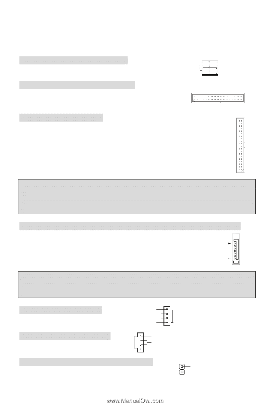
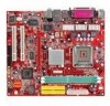
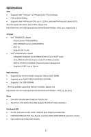
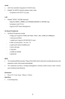
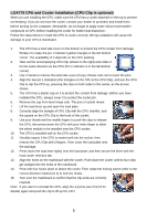
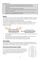
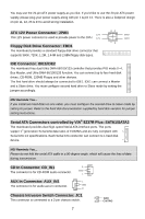
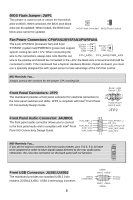
You may use the 20-pin ATX power supply as you like. If you'd like to use the 20-pin ATX power supply, please plug your power supply along with pin 1 & pin 13. There is also a foolproof design on pin 11, 12, 23 & 24 to avoid wrong installation. ATX 12V Power Connector: JPW1 12V This 12V power connector is used to provide power to the CPU. 12V Floppy Disk Drive Connector: FDD1 The mainboard provides a standard floppy disk drive connector that supports 360K, 720K, 1.2M, 1.44M and 2.88M floppy disk types. 42 31 GND GND IDE Connector: IDE1/IDE2 The mainboard has dual Ultra DMA 66/100/133 controller that provides PIO mode 0~4, Bus Master, and Ultra DMA 66/100/133 function. You can connect up to four hard disk drives, CD-ROM, 120MB Floppy and other devices. The first hard drive should always be connected to IDE1. IDE1 can connect a Master and a Slave drive. You must configure second hard drive to Slave mode by setting the jumper accordingly. MSI Reminds You... If you install two hard disks on one cable, you must configure the second drive to Slave mode by setting its jumper. Refer to the hard disk documentation supplied by hard disk vendors for jumper setting instructions. Serial ATA Connectors controlled by VIA® 8237R Plus: SATA1/SATA2 The mainboard provides dual high-speed Serial ATA interface ports. The ports supper 1st generation Serial ATA data rates of 150MB/s and are fully compliant with Serial ATA 1.0 specifications. Each Serial ATA connector can connect to 1 hard disk device. MSI Reminds You... Please do not fold the serial ATA cable in a 90-degree angle, which will cause the loss of data during transmission. CD In Connector: CD_IN1 R The connector is for CD-ROM audio connector. GND L AUX In Connector: AUX_IN1 L The connector is for audio aux-in connector. GND R Chassis Intrusion Switch Connector: JC1 This connector is connected to a 2-pin chassis switch. 2 GND 1 CINTRO 7
-
 1
1 -
2
-
3
-
4
-
5
-
6
-
7
-
 8
8 -
 9
9 -
 10
10 -
 11
11 -
 12
12 -
 13
13 -
 14
14 -
 15
15 -
 16
16 -
 17
17 -
 18
18 -
19
-
20
-
21
-
22
-
23
-
24
-
25
-
26
-
27
-
28
-
29
-
30
-
31
-
32
-
33
-
34
-
35
-
36
-
37
-
38
-
39
-
40
-
41
-
42
-
43
-
44
-
45
-
46
-
47
-
48
-
49
-
50
-
51
-
52
-
53
-
54
-
55
-
56
-
57
-
58
-
59
-
60
-
61
-
62
-
63
-
64
-
65
-
66
-
67
-
68
-
69
-
70
-
71
-
72
-
73
-
74
-
75
-
76
-
77
-
78
-
79
-
80
-
81
-
82
-
83
-
84
-
85
-
86
-
87
-
88
-
89
-
90
-
91
-
92
-
93
-
94
-
95
 |
 |