MSI PM8M3-V User Guide - Page 14
Fan Power Connectors: CPUFAN1/SYSFAN1/PWRFAN1 - bios update
 |
UPC - 816909014624
View all MSI PM8M3-V manuals
Add to My Manuals
Save this manual to your list of manuals |
Page 14 highlights
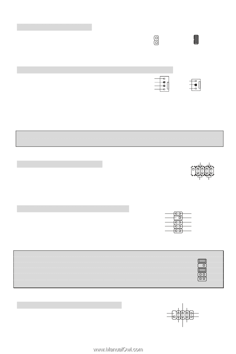
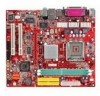
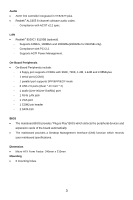
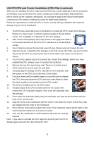
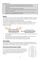
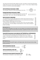
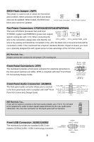
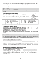
BIOS Flash Jumper: JWP1 This jumper is used to lock or unlock the boot block area on BIOS. When unlocked, the BIOS boot block area can be updated. When locked, the BIOS boot block area cannot be updated. 2 2 1 1 BIOS Flash Unlocked BIOS Flash Locked Fan Power Connectors: CPUFAN1/SYSFAN1/PWRFAN1 The 4-pin CPUFAN1 (processor fan) and 3-pin SYSFAN1 (system fan)/PWRFAN1 (power fan) support system cooling fan with +12V. When connecting the wire to the connectors, always take note that the red Control Sensor +12V GND CPU_FAN1 Sensor +12V GND SY S _ FAN 1/ PWR _FAN wire is the positive and should be connected to the +12V, the black wire is Ground and should be connected to GND. If the mainboard has a System Hardware Monitor chipset on-board, you must use a specially designed fan with speed sensor to take advantage of the CPU fan control. MSI Reminds You... Always consult the vendors for the proper CPU cooling fan. Front Panel Connectors: JFP2 The mainboard provides a front panel connector for electrical connection to the front panel switches and LEDs. JFP2 is compliant with Intel® Front Panel I/O Connectivity Design Guide. Reset HDD Switch LED 9 1 10 2 PowerPower Switch LED JFP2 Front Panel Audio Connector: JAUDIO1 The front panel audio connector allows you to connect to the front panel audio and is compliant with Intel® Front Panel I/O Connectivity Design Guide. AUD_RET_L Key AUD_RET_R AUD_VCC AUD_GND 10 9 21 AUD_FPOUT_L HP_ON AUD_FPOUT_R AUD_MIC_BIAS AUD_MIC MSI Reminds You... 10 9 If you do not want to connect to the front audio header, pins 5 & 6, 9 & 10 have to be jumpered in order to have signal output directed to the rear audio ports. Otherwise, the Line-Out connector on the back panel will not function. 21 Front USB Connector: JUSB1/JUSB2 The mainboard provides two standard USB 2.0 pin headers JUSB1&JUSB2. USB2.0 technology increases 8 (9)Key (10)USB0C USB0+ GND USB0- VCC(1) VCC(2) GND USB1USB1+
-
 1
1 -
2
-
3
-
4
-
5
-
6
-
7
-
8
-
 9
9 -
 10
10 -
 11
11 -
 12
12 -
 13
13 -
 14
14 -
 15
15 -
 16
16 -
 17
17 -
 18
18 -
 19
19 -
20
-
21
-
22
-
23
-
24
-
25
-
26
-
27
-
28
-
29
-
30
-
31
-
32
-
33
-
34
-
35
-
36
-
37
-
38
-
39
-
40
-
41
-
42
-
43
-
44
-
45
-
46
-
47
-
48
-
49
-
50
-
51
-
52
-
53
-
54
-
55
-
56
-
57
-
58
-
59
-
60
-
61
-
62
-
63
-
64
-
65
-
66
-
67
-
68
-
69
-
70
-
71
-
72
-
73
-
74
-
75
-
76
-
77
-
78
-
79
-
80
-
81
-
82
-
83
-
84
-
85
-
86
-
87
-
88
-
89
-
90
-
91
-
92
-
93
-
94
-
95
 |
 |