MSI PM8M3-V User Guide - Page 12
Memory, Power Supply, ATX 24-Pin Power Connector: CONN1 - bios
 |
UPC - 816909014624
View all MSI PM8M3-V manuals
Add to My Manuals
Save this manual to your list of manuals |
Page 12 highlights
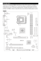
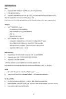
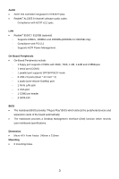
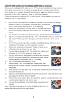
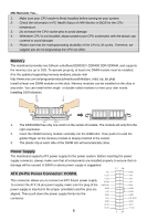
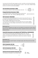
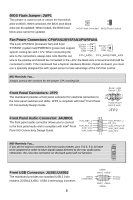
MSI Reminds You... 1. Make sure your CPU cooler is firmly installed before turning on your system. 2. Check the information in PC Health Status of H/W Monitor in BIOS for the CPU temperature. 3. Do not touch the CPU socket pins to avoid damage. 4. Whenever CPU is not installed, always protect your CPU socket pins with the plastic cap covered to avoid damage. 5. Please note that the mating/unmating durability of the CPU is 20 cycles. Therefore, we suggest you do not plug/unplug the CPU too often. Memory The mainboard provides two 184-pin unbuffered DDR333 / DDR400 DDR SDRAM, and supports the memory size up to 2GB. To operate properly, at least one DIMM module must be installed. (For the updated supporting memory modules, please visit http://www.msi.com.tw/program/products/mainboard/mbd/pro_mbd_trp_list.php) Install at least one DIMM module on the slots. Memory modules can be installed on the slots in any order. You can install either single- or double-sided modules to meet your own needs. Installing DDR Modules Volt Notch 1. The DDR DIMM has only one notch on the center of module. The module will only fit in the right orientation. 2. Insert the DIMM memory module vertically into the DIMM slot. Then push it in until the golden finger on the memory module is deeply inserted in the socket. 3. The plastic clip at each side of the DIMM slot will automatically close. Power Supply The mainboard supports ATX power supply for the power system. Before inserting the power supply connector, always make sure that all components are installed properly to ensure that no damage will be caused. A 300W or above power supply is suggested. 12 24 ATX 24-Pin Power Connector: CONN1 This connector allows you to connect an ATX 24-pin power supply. To connect the ATX 24-pin power supply, make sure the plug of the power supply is inserted in the proper orientation and the pins are aligned. Then push down the power supply firmly into the connector. 6 NC +12V +12V 5VSB PWR OK GND +5V GND +5V GND +3.3V +3.3V 1 13 GND +5V +5V +5V Res GND GND GND PS-ON# GND -12V +3.3V
-
 1
1 -
2
-
3
-
4
-
5
-
6
-
 7
7 -
 8
8 -
 9
9 -
 10
10 -
 11
11 -
 12
12 -
 13
13 -
 14
14 -
 15
15 -
 16
16 -
 17
17 -
18
-
19
-
20
-
21
-
22
-
23
-
24
-
25
-
26
-
27
-
28
-
29
-
30
-
31
-
32
-
33
-
34
-
35
-
36
-
37
-
38
-
39
-
40
-
41
-
42
-
43
-
44
-
45
-
46
-
47
-
48
-
49
-
50
-
51
-
52
-
53
-
54
-
55
-
56
-
57
-
58
-
59
-
60
-
61
-
62
-
63
-
64
-
65
-
66
-
67
-
68
-
69
-
70
-
71
-
72
-
73
-
74
-
75
-
76
-
77
-
78
-
79
-
80
-
81
-
82
-
83
-
84
-
85
-
86
-
87
-
88
-
89
-
90
-
91
-
92
-
93
-
94
-
95
 |
 |