MSI X58 PLATINUM User Guide - Page 30
Fan Power Connectors: CPUFAN, SYSFAN1~5, IEEE1394 Connector: J1394_1 Optional - processor
 |
UPC - 816909051629
View all MSI X58 PLATINUM manuals
Add to My Manuals
Save this manual to your list of manuals |
Page 30 highlights
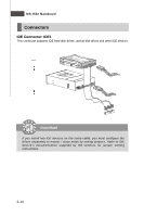
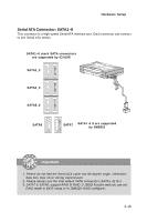
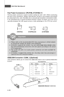
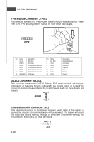
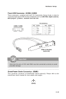
MS-7522 Mainboard Fan Power Connectors: CPUFAN, SYSFAN1~5 The fan power connectors support system cooling fan with +12V. W hen connecting the wire to the connectors, always note that the red wire is the positive and should be connected to the +12V; the black wire is Ground and should be connected to GND. If the mainboard has a System Hardware Monitor chipset on-board, you must use a specially designed fan with speed sensor to take advantage of the CPU fan control. CONTROL S E NS OR +1 2V GND CPUFAN1 SE NS OR +1 2V GND SYSFAN1/2/3 Important NC +1 2V GND SYSFAN4/5 1. Please refer to the recommended CPU fans at processor's official website or consult the vendors for proper CPU cooling fan. 2. CPUFAN1 supports fan control. You can install Dual Core Center utility that will automatically control the CPU fan speed according to the actual CPU temperature. 3. Fan cooler set with 3 or 4 pins power connector are both available for CPUFAN1. 4. SYSFAN1~3 support fan control, too. You may select how percentage of speed for the SYS FAN1/2/3 in BIOS. IEEE1394 Connector: J1394_1 (Optional) This connector allows you to connect the IEEE1394 device via an optional IEEE1394 bracket. Pin Definition J1394_1 2 10 1 9 PIN SIGNAL PIN 1 TPA+ 2 3 Ground 4 5 TPB+ 6 7 Cable power 8 9 Key (no pin) 10 SIGNAL TPAGround TPBCable power Ground 2-16 IEEE1394 Bracket (Optional)
-
 1
1 -
2
-
3
-
4
-
5
-
6
-
7
-
8
-
9
-
10
-
11
-
12
-
13
-
14
-
15
-
16
-
17
-
18
-
19
-
20
-
21
-
22
-
23
-
24
-
 25
25 -
 26
26 -
 27
27 -
 28
28 -
 29
29 -
 30
30 -
 31
31 -
 32
32 -
 33
33 -
 34
34 -
 35
35 -
36
-
37
-
38
-
39
-
40
-
41
-
42
-
43
-
44
-
45
-
46
-
47
-
48
-
49
-
50
-
51
-
52
-
53
-
54
-
55
-
56
-
57
-
58
-
59
-
60
-
61
-
62
-
63
-
64
-
65
-
66
-
67
-
68
-
69
-
70
-
71
-
72
-
73
-
74
-
75
-
76
-
77
-
78
-
79
-
80
-
81
-
82
-
83
-
84
-
85
-
86
-
87
-
88
-
89
-
90
-
91
-
92
-
93
-
94
-
95
-
96
-
97
-
98
-
99
-
100
-
101
-
102
-
103
-
104
-
105
-
106
-
107
-
108
-
109
-
110
-
111
-
112
-
113
-
114
-
115
-
116
-
117
-
118
-
119
-
120
-
121
-
122
-
123
-
124
-
125
-
126
-
127
-
128
-
129
-
130
-
131
-
132
-
133
-
134
-
135
-
136
-
137
-
138
-
139
-
140
-
141
 |
 |
