MSI X58 PLATINUM User Guide - Page 32
TPM Module Connector: JTPM1, D-LED2 Connector: JDLED1, Chassis Intrusion Connector: JCI1
 |
UPC - 816909051629
View all MSI X58 PLATINUM manuals
Add to My Manuals
Save this manual to your list of manuals |
Page 32 highlights
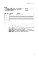
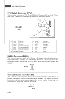
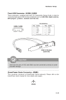
MS-7522 Mainboard TPM Module Connector: JTPM1 This connector connects to a TPM (Trusted Platform Module) module (optional). Please refer to the TPM security platform manual for more details and usages. 2 14 1 13 JTPM 1 Pin Signal Description 1 LCLK LPC clock 3 LRST# LPC reset 5 LAD0 LPC address & data pin0 7 LAD1 LPC address & data pin1 9 LAD2 LPC address & data pin2 11 LAD3 LPC address & data pin3 13 LFRAME# LPCFrame Pin Signal 2 3V_STB 4 VCC3 6 SIRQ 8 VCC5 10 KEY 12 GND 14 GND Description 3V standby power 3.3V power Serial IRQ 5V power No pin Ground Ground D-LED2 Connector: JDLED1 This connector connects to a D-LED2 (Debug-LED2) panel (optional), which shows information on the panel for you and identify the current status or mode of the connected system. Please refer to the D-LED2 quick guide for more details and usages. 12 11 JDLED1 21 Chassis Intrusion Connector: JCI1 This connector connects to the chassis intrusion switch cable. If the chassis is opened, the chassis intrusion mechanism will be activated. The system will record this status and show a warning message on the screen. To clear the warning, you must enter the BIOS utility and clear the record. GND 2 CINTRU 1 JCI1 2-18
-
 1
1 -
2
-
3
-
4
-
5
-
6
-
7
-
8
-
9
-
10
-
11
-
12
-
13
-
14
-
15
-
16
-
17
-
18
-
19
-
20
-
21
-
22
-
23
-
24
-
25
-
26
-
 27
27 -
 28
28 -
 29
29 -
 30
30 -
 31
31 -
 32
32 -
 33
33 -
 34
34 -
 35
35 -
 36
36 -
 37
37 -
38
-
39
-
40
-
41
-
42
-
43
-
44
-
45
-
46
-
47
-
48
-
49
-
50
-
51
-
52
-
53
-
54
-
55
-
56
-
57
-
58
-
59
-
60
-
61
-
62
-
63
-
64
-
65
-
66
-
67
-
68
-
69
-
70
-
71
-
72
-
73
-
74
-
75
-
76
-
77
-
78
-
79
-
80
-
81
-
82
-
83
-
84
-
85
-
86
-
87
-
88
-
89
-
90
-
91
-
92
-
93
-
94
-
95
-
96
-
97
-
98
-
99
-
100
-
101
-
102
-
103
-
104
-
105
-
106
-
107
-
108
-
109
-
110
-
111
-
112
-
113
-
114
-
115
-
116
-
117
-
118
-
119
-
120
-
121
-
122
-
123
-
124
-
125
-
126
-
127
-
128
-
129
-
130
-
131
-
132
-
133
-
134
-
135
-
136
-
137
-
138
-
139
-
140
-
141
 |
 |
