Mackie 802-VLZ4 Owners Manual - Page 6
Hookup Diagrams - powered speakers
 |
View all Mackie 802-VLZ4 manuals
Add to My Manuals
Save this manual to your list of manuals |
Page 6 highlights
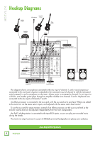
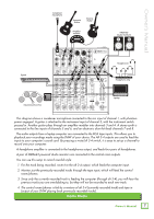
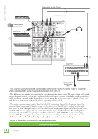
802VLZ4 Hookup Diagrams Electric Guitar Acoustic Microphone Guitar Bass Guitar Amplifier modeler DI Box Effects Processor Return (connected to aux send) Send Return Vocal Compressor (connected to Insert) Send Return Compressor (connected to Insert) Keyboards iPodTM Docking Station SRM650 Powered Speakers This diagram shows a microphone connected to the mic input of channel 1, and a vocal compressor connected to the insert jack. A guitar is attached to the instrument input of channel 2, with the instrument switch pressed in, and a compressor on the insert. A bass guitar is connected to channel 3's mic input via a DI box, and another guitar plays through an amplifier modeler into channels 5 and 6. Keyboards are connected to the line inputs of channels 7 and 8. An effects processor is connected to the aux send, with the aux send set to post-level. Effects are added to the main mix via the stereo return inputs, and adjusted with the stereo return level control. To use the aux send for stage monitors instead of an effects processor, set the aux to pre-level so the monitor volume level can be adjusted independently from the main loudspeakers. An iPodTM docking station is connected to the tape RCA inputs, so you can play pre-recorded music during the breaks. The main mix output connects to a pair of SRM650 powered loudspeakers to please your audience. 6 802VLZ4 Live Band PA System
-
 1
1 -
 2
2 -
 3
3 -
 4
4 -
 5
5 -
 6
6 -
 7
7 -
 8
8 -
 9
9 -
 10
10 -
 11
11 -
 12
12 -
13
-
14
-
15
-
16
-
17
-
18
-
19
-
20
-
21
-
22
-
23
-
24
-
25
-
26
-
27
-
28
 |
 |
