Mackie MS1202-VLZ Owner's Manual - Page 26
Modifications
 |
View all Mackie MS1202-VLZ manuals
Add to My Manuals
Save this manual to your list of manuals |
Page 26 highlights
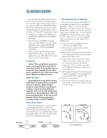
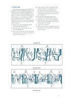
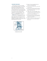
MODIFICATIONS BEFORE For most folks, the MS1202-VLZ works just fine the way it is. But for special applications, there are three signal routing changes that can be performed easily on the MS1202-VLZ. Easy for someone with soldering experience, that is. If you don't know how to solder, find a technician that can. This is NOT a good place to learn! • Modification A changes AUX SEND 2 to be pre-fader, pre-mute instead of post-fader, post-mute. • Mod B changes AUX SEND 1 (in post mode) and AUX SEND 2 to receive signal regardless of the channel's MUTE/ALT switch position, but still be post-fader (GAIN knob). • Mod C changes the SOURCE matrix's MAIN MIX selection to tap the stereo signal before the MAIN MIX level control (pre) instead of after (post). UL Warning Caution! These modification instructions are for use by qualified personnel only. To avoid electric shock, do not perform any servicing other than changing the fuse unless you are qualified to do so. Refer all servicing and modifying to qualified personnel. Mackie Disclaimer Any modification of any Mackie Designs product must be performed by a competent electronic technician. Mackie Designs accepts no responsibility for any damages or injuries caused by any modification, regardless of the source of the modification instructions or the qualifications of the technician performing them. In the case of such damages, Mackie Designs may declare warranty privileges void. BE CAREFUL! 1. PRE-FADER MOD (AUX TO MONITOR) This modification changes AUX SEND 2 to be pre-fader, pre-mute instead of post-fader, post-mute. ("Fader" refers to the channel GAIN knob, and "Mute" refers to the channel's MUTE/ALT 3-4 switch.) In order to convert the entire mixer, it must be done on each channel. Is slightly more involved for the stereo channels 5-12. The work area is on the underside of the circuit board, near the channel AUX SEND knobs. 1. Remove all cords, including the power cable, from the MS1202-VLZ. 2. Place the mixer upside-down on a dry, non-marring surface. 3. Remove the screws that attach the bottom cover. Keep track of what screws go where. Remove the bottom cover. 4. Using a sharp "X-acto" type knife, cut the conductor at point 'A' (channels 1-4) or the conductors at points 'AL' and 'AR' (channels 5-12). Be careful to cut all the way through the conductor, and do not cut any nearby traces. 5. Add a jumper from point 'B' to the square pad at point 'A' (channels 1-4) or from points 'BL' to 'AL' and 'BR' to 'AR' (channels 5-12). 6. Repeat for all channels. 7. Check your work very carefully, then put the bottom cover back the way you found it. You're done! A Note About Jumpers When installing jumpers, do not run their ends through holes in the circuit board. Rather, solder them flat against the desired pad (the flat silver area, possibly with a hole in the middle). Make sure the ends of these flat wires do not extend beyond the pad. Jumper AFTER Solder Ch.'s 1-4 5 jumper B here 4 cut A here Ch.'s 5-12 5 jumper here BR BL AL 4 cut AR here #1: Pre-Fader Mod Holes 26
-
 1
1 -
2
-
3
-
4
-
5
-
6
-
7
-
8
-
9
-
10
-
11
-
12
-
13
-
14
-
15
-
16
-
17
-
18
-
19
-
20
-
 21
21 -
 22
22 -
 23
23 -
 24
24 -
 25
25 -
 26
26 -
 27
27 -
 28
28 -
 29
29 -
 30
30 -
 31
31 -
32
-
33
-
34
-
35
-
36
-
37
-
38
-
39
-
40
-
41
-
42
-
43
-
44
-
45
-
46
-
47
-
48
-
49
-
50
 |
 |
