Magnavox 27MS4504 User manual, English (US) - Page 10
Sing The, Omponent - manual
 |
View all Magnavox 27MS4504 manuals
Add to My Manuals
Save this manual to your list of manuals |
Page 10 highlights
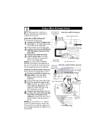
6 USING THE CVI (COMPONENT VIDEO INPUT) JACKS Component Video inputs provide for the highest possible color and picture resolution in the playback of digital signal source material, such as with DVD players. The color difference signals (Pb, Pr) and the luminance signal (Y) connected and received separately, which allows for improved color bandwidth information (not possible when using composite video or S-Video connections). 1 Connect the Component (Y, Pb, Pr) Video OUT jacks from the DVD player (or similar device) to the (Y, Pb, Pr) in(put) jacks on the TV. When using the Component Video Inputs, it is best not to connect a signal to the AV1 IN Video Jack. 2 Connect the red and white AUDIO CABLES to the Audio (left and right) output jacks on the rear of the accessory device to the Audio (L and R) AV1 IN Input Jacks on the TV. 3 Turn the TV and the DVD (or digital accessory device) ON. 4 Press the CH + or CH- buttons to set the TV to its CVI channel. (Go to your lowest channel, for example channel 1, then change channels down to find the correct source channel.) 5 Insert a DVD disc into the DVD player and press the PLAY ᮣ button on the DVD Player. The CVI connection will be dominate over the AV1 in Video Input. When a Component Video Device is connected as described, it is best not to have a video signal connected to the AV1 in Video Input jack. Back of TV 1 Monitor out AV1 in VIDEO Y L/Mono AUDIO Pb 2 AV2 in R Pr COMPONENT VIDEO INPUT S-VIDEO Component Video Cables (Green, Blue, Red) COMP VIDEO Y Pb Pr S-VIDEO VIDEO AUDIO R OUT OUT OUT Audio L Cables (Red and White) 3 Accessory Device 5 Equipped with Component Video Outputs. HELPFUL HINT The description for the component video connectors may differ depending on the DVD player or accessory digital source equipment used (for example, Y, Pb, Pr; Y, B-Y, R-Y; Y, Cr, Cb). Although abbreviations and terms may vary, the letters b and r stand for the blue and red color component signal connectors, and Y indicates the luminance signal. Refer to your DVD or digital accessory owner's manual for definitions and connection details. Note: Cables are not supplied with the TV, but are available from Magnavox or electronics retailers.
-
 1
1 -
2
-
3
-
4
-
 5
5 -
 6
6 -
 7
7 -
 8
8 -
 9
9 -
 10
10 -
 11
11 -
 12
12 -
 13
13 -
 14
14 -
 15
15 -
16
-
17
-
18
-
19
-
20
-
21
-
22
-
23
-
24
-
25
-
26
-
27
-
28
-
29
-
30
-
31
-
32
-
33
-
34
-
35
-
36
 |
 |
