Magnavox MDV453 User Manual - Page 12
Connecting to a TV only, TV has, COMPONENT VIDEO IN, Jacks
 |
UPC - 037849937457
View all Magnavox MDV453 manuals
Add to My Manuals
Save this manual to your list of manuals |
Page 12 highlights
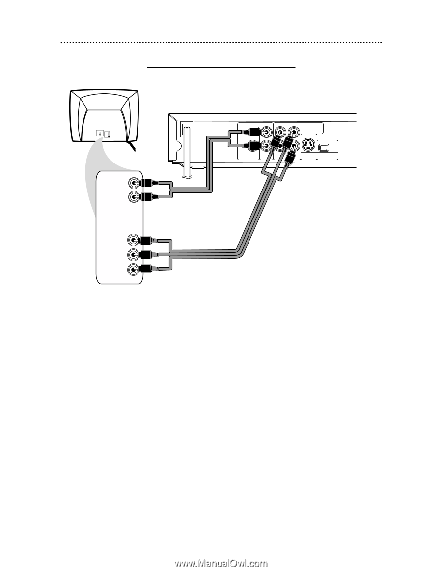
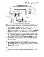
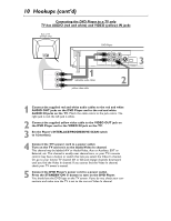
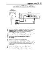
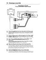
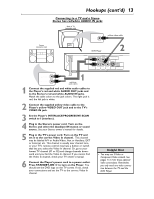
12 Hookups (cont'd) Back of TV (example only) Connecting to a TV only TV has COMPONENT VIDEO IN Jacks LEFT AUDIO IN RIGHT AUDIO IN VIDEO IN LEFT AUDIO IN RIGHT AUDIO IN DVD Player AUDIO OUT L DIGITAL AUDIO OUT PCM / BITSTREAM Y Pr/Cr COMPONENT VIDEO OUT IP COAXIAL R VIDEO Pb/Cb S-VIDEO PROGRESSIVE OUT OUT 3 1 COMPONENT VIDEO IN Y Pr/Cr Pb/Cb 2 1 Connect the supplied red and white audio cables to the Player's red and white AUDIO OUT jacks and to the TV's red and white AUDIO IN jacks. Match the cable colors to the jack colors. The right jack is red; the left jack is white. 2 Connect component video cables (not supplied) to the Player's COMPONENT VIDEO OUT jacks (Y Pr/Cr Pb/Cb) and to the TV's COMPONENT VIDEO IN jacks. The jacks on the Player are green, red, and blue. 3 If your TV is compatible with progressive scanning (480p), set the Player's INTERLACE/PROGRESSIVE SCAN switch to P (Progressive). If your TV does not have Progressive Scan, set the Player's INTERLACE/PROGRESSIVE SCAN switch to I (Interlace). 4 Plug in the TV's power cord. Turn on the TV and set it to the Component Video In channel, which may be near channel zero. Go to your lowest TV channel (01 or 02) and change channels downward until you find the Component Video In channel. Or, your TV's remote control may have a button or switch that lets you select the Component Video In channel. If you cannot find it, check your TV owner's manual. 5 Connect the DVD Player's power cord to a power outlet. Press the STANDBY-ON y button to turn on the Player. You should see the DVD logo on the TV screen. If you do not, check your connections and make sure the TV is on the correct Component Video In channel.
-
 1
1 -
2
-
3
-
4
-
5
-
6
-
 7
7 -
 8
8 -
 9
9 -
 10
10 -
 11
11 -
 12
12 -
 13
13 -
 14
14 -
 15
15 -
 16
16 -
 17
17 -
18
-
19
-
20
-
21
-
22
-
23
-
24
-
25
-
26
-
27
-
28
-
29
-
30
-
31
-
32
-
33
-
34
-
35
-
36
-
37
-
38
-
39
-
40
-
41
-
42
-
43
-
44
-
45
-
46
-
47
-
48
 |
 |