Magnavox MDV453 User Manual - Page 19
Rear Panel
 |
UPC - 037849937457
View all Magnavox MDV453 manuals
Add to My Manuals
Save this manual to your list of manuals |
Page 19 highlights
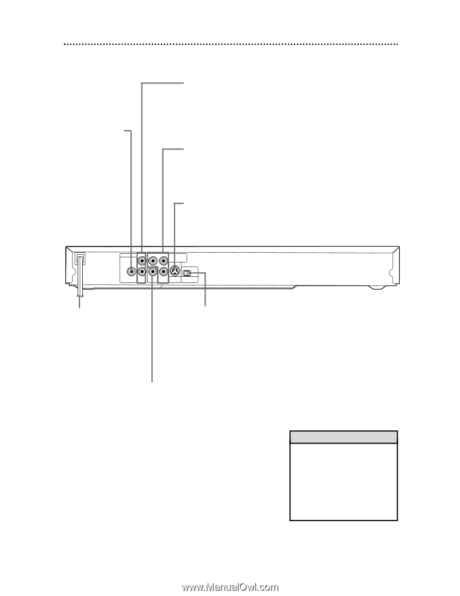
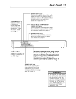
Rear Panel 19 COAXIAL Jack Connect an optional digital audio coaxial cable here and to the Coaxial Digital Audio In jack of a stereo. Details are on page 14. AUDIO OUT Jacks Connect the supplied red and white audio cables here and to the Audio In jacks of a television, stereo, or RF modulator. Match the cable colors to the jack colors. Details are on pages nine - 13. Y Pr/Cr Pb/Cb COMPONENT VIDEO OUT Jacks Connect optional component video cables here and to the component Video In jacks of a television. Details are on page 12. S-VIDEO OUT Jack Connect an optional S-Video cable here and to the S-Video In jack of a television. Details are on page 11. AUDIO OUT L DIGITAL AUDIO OUT PCM / BITSTREAM Y Pr/Cr COMPONENT VIDEO OUT IP COAXIAL R VIDEO Pb/Cb S-VIDEO PROGRESSIVE OUT OUT AC Power Cord Connect to a standard AC outlet to supply power to the DVD Player. INTERLACE/PROGRESSIVE SCAN Switch Set to Interlace (I) or Progressive Scan (P). Set the switch to P (Progressive Scan) only if you connected the Player's Y Pr/Cr Pb/Cb COMPONENT VIDEO OUT jacks to a TV with Progressive Scan. Otherwise, set the switch to I (Interlace) or you will not have a picture at the TV. Details are on page 12. VIDEO OUT Jack Connect the supplied yellow video cable here and to the Video In jack of a TV or RF modulator. Details are on pages nine, 10, 13, and 14. Helpful Hint • You only need one audio connection and one video connection, so you will not have a cable connected to every jack. For example, if you are using the S-VIDEO OUT jack, you will not use the yellow VIDEO OUT jack or the Y Pr/Cr Pb/Cb COMPONENT VIDEO OUT jacks.
-
 1
1 -
2
-
3
-
4
-
5
-
6
-
7
-
8
-
9
-
10
-
11
-
12
-
13
-
 14
14 -
 15
15 -
 16
16 -
 17
17 -
 18
18 -
 19
19 -
 20
20 -
 21
21 -
 22
22 -
 23
23 -
 24
24 -
25
-
26
-
27
-
28
-
29
-
30
-
31
-
32
-
33
-
34
-
35
-
36
-
37
-
38
-
39
-
40
-
41
-
42
-
43
-
44
-
45
-
46
-
47
-
48
 |
 |