Makita AT2550A Owners Manual - Page 6
Operation
 |
View all Makita AT2550A manuals
Add to My Manuals
Save this manual to your list of manuals |
Page 6 highlights
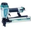
2. Insert strip of staples into the magazine. Two strips of staples can be loaded. 007212 OPERATION CAUTION: • Make sure all safety systems are in working order before operation. 1. Pull the trigger first and then place the contact element against the workpiece. 007199 1. Trigger 1 2. Contact element 3. Workpiece 3. Depress the lock pin lightly and pull the pusher to unhook it. With the lock pin depressed, return the pusher 2 slowly and gently to the original position. Keep depressing the pusher until it passes through. 007213 1. Pusher 1 3 007198 1. Trigger 2. Contact element 3. Workpiece 2 3 1 Connecting air hose 1 007197 1. Air fitting 2. Air socket 2. To drive a staple, you may place the contact element against the workpiece and pull the trigger, or No. 1 method is for continuous stapling. No. 2 method is for intermittent stapling, when you wish to drive a staple carefully and very accurately. 2 Slip the air socket of the air hose onto the air fitting on the stapler. Be sure that the air socket locks firmly into position when installed onto the air fitting. A hose coupling must be installed on or near the tool in such a way that the pressure reservoir will discharge at the time the air supply coupling is disconnected. CAUTION: • However when the tool is set to the "Intermittent Staplling" mode, WITH THE TRIGGER HELD IN A HALF-PULLED POSITION, an unexpected stapling could occur, if contact element is allowed to re-contact against the workpiece or the other surface under the influence of recoil. In order to avoid this unexpected stapling, perform as follows; A. Do not place the contact element against the workpiece with excessive force. B. Pull the trigger fully and hold it on for 1-2 seconds after stapling. For No. 2 method, the OPTIONAL SEQUENTIAL TRIP TRIGGER (SINGLE SHOT PART) is used . Replace the trigger part with this. 6
-
 1
1 -
 2
2 -
 3
3 -
 4
4 -
 5
5 -
 6
6 -
 7
7 -
 8
8 -
 9
9 -
 10
10 -
 11
11 -
 12
12 -
13
-
14
-
15
-
16
-
17
-
18
-
19
-
20
-
21
-
22
-
23
-
24
-
25
-
26
-
27
-
28
 |
 |
