Makita RP2301FC Owners Manual - Page 4
Save These Instructions., Symbols, Functional Description - manual
 |
View all Makita RP2301FC manuals
Add to My Manuals
Save this manual to your list of manuals |
Page 4 highlights
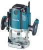
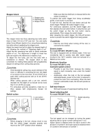
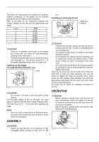
9. Make sure the bit is not contacting the workpiece before the switch is turned on. 10. Before using the tool on an actual workpiece, let it run for a while. Watch for vibration or wobbling that could indicate improperly installed bit. 11. Be careful of the bit rotating direction and the feed direction. 12. Do not leave the tool running. Operate the tool only when hand-held. 13. Always switch off and wait for the bit to come to a complete stop before removing the tool from workpiece. 14. Do not touch the bit immediately after operation; it may be extremely hot and could burn your skin. 15. Do not smear the tool base carelessly with thinner, gasoline, oil or the like. They may cause cracks in the tool base. 16. Draw attention to the need to use cutters of the correct shank diameter and which are suitable for the speed of the tool. 17. Some material contains chemicals which may be toxic. Take caution to prevent dust inhalation and skin contact. Follow material supplier safety data. 18. Always use the correct dust mask/respirator for the material and application you are working with. SAVE THESE INSTRUCTIONS. WARNING: MISUSE or failure to follow the safety rules stated in this instruction manual may cause serious personal injury. USD201-2 Symbols The followings show the symbols used for tool. ・ volts ・ amperes ・ hertz ・ alternating current ・ no load speed ・ Class II Construction ・ revolutions or reciprocation per minute FUNCTIONAL DESCRIPTION CAUTION: • Always be sure that the tool is switched off and unplugged before adjusting or checking function on the tool. Adjusting the depth of cut 1 2 3 4 5 6 009857 1. Adjusting knob 7 2. Lock lever 8 3. Stopper pole setting nut 4. Fast-feed button 5. Adjusting bolt 6. Stopper block 7. Depth pointer 8. Stopper pole Place the tool on a flat surface. Loosen the lock lever and lower the tool body until the bit just touches the flat surface. Tighten the lock lever to lock the tool body. Turn the stopper pole setting nut counterclockwise. Lower the stopper pole until it makes contact with the adjusting bolt. Align the depth pointer with the "0" graduation. The depth of cut is indicated on the scale by the depth pointer. While pressing the fast-feed button, raise the stopper pole until the desired depth of cut is obtained. Minute depth adjustments can be obtained by turning the adjusting knob (1 mm (3/64") per turn). By turning the stopper pole setting nut clockwise, you can fasten the stopper pole firmly. Now, your predetermined depth of cut can be obtained by loosening the lock lever and then lowering the tool body until the stopper pole makes contact with the adjusting hex bolt of the stopper block. Nylon nut 1 1. Nylon nut 009855 The upper limit of the tool body can be adjusted by turning the nylon nut. CAUTION: Do not lower the nylon nut too low. The bit will protrude dangerously. 4
-
 1
1 -
 2
2 -
 3
3 -
 4
4 -
 5
5 -
 6
6 -
 7
7 -
 8
8 -
 9
9 -
 10
10 -
11
-
12
-
13
-
14
-
15
-
16
-
17
-
18
-
19
-
20
-
21
-
22
-
23
-
24
-
25
-
26
-
27
-
28
-
29
-
30
-
31
-
32
 |
 |
