Marantz SR4000 Service Manual - Page 9
Dismantling Hints
 |
View all Marantz SR4000 manuals
Add to My Manuals
Save this manual to your list of manuals |
Page 9 highlights
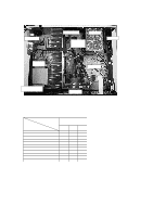
DISMANTLING HINTS Dismantling of Front 2-1 Dismantling of mono board 1) Remove front . See picture 1 2) Remove whole front (disconnect the wires on the mono board coming from front) 2-1 Service position monoboard 1) Bring front in position as shown in picture 6 2) Snap nok of front in bottom to make front stable . See picture 7 3) Connect front wiring back to monoboard. *The tuner module doesn't have to be connected. Use an other source (pe.CD) Power rod 1 snap 2 1 1 snap snap 1) Remove top cover 2) Remove power rod 3) Remove 6 x screw as shown in picture 1 4) Release two snaps (left & right side front) 5) Release two snaps on the bottom side front 6) Tipp down front as shown in picture 2 Dismantling of mainstrafo 1 snap 2 picture 1 2 2 3 2 2 2 3 picture 3a picture 3b (SR3000) (SR4000) 3) Remove 8 (SR3000) x screws shown in mentionned aria . See picture 3a 3) Remove 12 (SR4000) x screws shown in mentionned aria . See picture 3b 1 cable-sleeve 1 1 1 1 1 Dpl bracket Service position main trafo 3 picture 4a (SR3000 Only) picture 6 picture 7 picture 2 1 1 Metal bracket 1 1 1 2 picture 4 4) Remove DPL bracket. See picture 4a (SR3000 Only) 5) Remove wires out the cable-sleeve. 6) Remove 7 x screw and remove metal bracket 7) Remove 2 x screw on mono board . See pictue 4 8) Remove mono board as shown arrow 1 & 2 . See picture 4 9) Bring the mono board in the service position as shown in picture 5 1) Put main trafo as shown in picture 9 Handling service cover 1 1 picture 9 1 1 1 1 1 1) Remove power rod 2) Remove 4x screw as shown in picture 8 picture 8 Legend 1 2 picture 5 = Torx M3x6mm ( screw with big head ) = Torx 3x10mm 3 = Torx M3x6mm 1 1 1 1 1 1 1 1 1 picture 10 1) To open the service cover cut 14 x lugs between cover and bottem . See picture 10 ( ) 2) To close the service cover put 12 x screw in mentionned holes. See picture 10 Service codenumber 12x Torx M3x6mm screw with big head = 4822 502 14659
-
 1
1 -
2
-
3
-
 4
4 -
 5
5 -
 6
6 -
 7
7 -
 8
8 -
 9
9 -
 10
10 -
 11
11 -
 12
12 -
 13
13 -
 14
14 -
15
-
16
-
17
-
18
-
19
-
20
-
21
-
22
-
23
-
24
-
25
-
26
-
27
-
28
-
29
-
30
-
31
-
32
-
33
-
34
-
35
-
36
-
37
-
38
-
39
-
40
-
41
-
42
-
43
-
44
-
45
-
46
-
47
-
48
-
49
-
50
-
51
-
52
-
53
-
54
-
55
-
56
-
57
-
58
-
59
-
60
-
61
-
62
-
63
-
64
-
65
-
66
-
67
-
68
-
69
-
70
-
71
-
72
-
73
-
74
-
75
-
76
-
77
 |
 |
