Marantz SR8000 Service Manual - Page 35
Alignment Procedures - 5 1 receiver
 |
View all Marantz SR8000 manuals
Add to My Manuals
Save this manual to your list of manuals |
Page 35 highlights
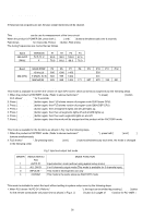
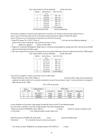
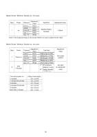
10. ALIGNMENT PROCEDURES 1. AM IF Adjustment Step Input Signal Source Connection Signal Frequency Source Signal Output Level and Modulation Reception Adjustment Adjustment Frequency Point Value 1 Signal generator output to transmission *loop antenna. (*:Standard required loop) 999 kHz (K, S, N) 1000 kHz (U) Level 300 µV/m (50dB/m) Mod. 400 Hz 30% Tuning point LA06 REMARK: For receiving antenna, the adapted one is available. This adjustment is not necessary normally, because the coil LA06 is preset by the original supplier. It is necessary when the incorrect usable sense and frequency response. 2. AM (MW) Tracking Adjustment Output level (L or R) Maximum at TAPE-OUT Step **Input Signal Source Signal Connection Frequency Source Signal Output Level and Modulation Reception Adjustment Adjustment Frequency Point Value 1 Signal generator output to transmission *loop antenna. (*:Standard required loop) 603 kHz (K, S, N) 600 kHz (U) Level 300 µV/m (50dB/m) Mod. 400 Hz 30% 603 kHz (K, S, N) 600 kHz (U) LA01 Output level (L or R) Maximum at TAPE-OUT 1404 kHz 2 (K, S, N) Level 300 µV/m (50dB/m) 1400 kHz Mod. 400 Hz 30% (U) 3 Repeat step 1 and 2 until sensitivity be maximized. 1404 kHz (K, S, N) 1400 kHz (U) CA01 Output level (L or R) Maximum at TAPE-OUT 3. AM (LW) Tracking Adjustment [N version] Step **Input Signal Source Signal Connection Frequency Source Signal Output Level and Modulation Reception Adjustment Adjustment Frequency Point Value Signal generator output to 1 transmission *loop antenna. 171 kHz (*:Standard required loop) Level 500 µV/m (54dB/m) Mod. 400 Hz 30% 171 kHz LA03 Output level (L or R) Maximum at TAPE-OUT 2 270 kHz Level 500 µV/m (54dB/m) Mod. 400 Hz 30% 270 kHz CA08 3 Repeat step 1 and 2 until sensitivity be maximized. 4. AM auto stop Adjustment Step Input Signal Source Connection Signal Frequency Source Signal Output Level and Modulation Reception Adjustment Adjustment Frequency Point Value Signal generator output to 999 kHz 1 transmission *loop antenna. (K, S, N) Level 500 µV/m (54 dB/m) (*:Standard required loop) 1000 kHz (U) 999 kHz (K, S, N) 1000 kHz (U) RA11 "TUNED" indicate on FLD 2 Level 1000 µV/m (60 dB/m) AUTO SCAN Only Confirm "TUNED" indicate on FLD 5. FM MONO. Distortion Adjustment Step Input Signal Source Connection Signal Frequency Source Signal Output Level and Modulation Level 500 µV (54 dB) MONO 1 kHz / 1 Signal generator output to 98 MHz Dev.40kHz 53.3% (K, S) FM antenna terminal. (75 Ω) (K, N, S, U) MONO 1 kHz / Dev. 75 kHz 100% (U, F) Reception Adjustment Adjustment Frequency Point Value 98 MHz (P2) MONO L201 Distortion level Minimum at TAPE-OUT 59
-
 1
1 -
2
-
3
-
4
-
5
-
6
-
7
-
8
-
9
-
10
-
11
-
12
-
13
-
14
-
15
-
16
-
17
-
18
-
19
-
20
-
21
-
22
-
23
-
24
-
25
-
26
-
27
-
28
-
29
-
 30
30 -
 31
31 -
 32
32 -
 33
33 -
 34
34 -
 35
35 -
 36
36 -
 37
37 -
 38
38 -
 39
39 -
 40
40 -
41
-
42
-
43
-
44
-
45
-
46
-
47
-
48
-
49
-
50
-
51
-
52
-
53
-
54
-
55
-
56
-
57
-
58
-
59
 |
 |
