Marantz SR8000 Service Manual - Page 36
Only Confirm
 |
View all Marantz SR8000 manuals
Add to My Manuals
Save this manual to your list of manuals |
Page 36 highlights
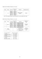
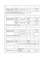
6. FM Muting Level Adjustment Turn the variable resistor R212 to no indication ("TUNED") point. And return that valuable resistor in opposite to the "TUNED" indicate point. Step Input Signal Source Connection Signal Frequency Source Signal Output Level and Modulation Reception Adjustment Adjustment Frequency Point Value 1 Signal generator output to FM antenna terminal. (75 Ω) 98 MHz Level 10 µV (20 dB) MONO 1 kHz / Dev.40 kHz 53.3% (K, N, S) MONO 1 kHz / Dev. 75 kHz 100% (U) 98 MHz (P2) R212 "TUNED" indicate on FLD 2 Over mentioned level +3 dB AUTO SCAN Only Confirm "TUNED" indicate on FLD 7. FM STEREO Distortion Adjustment Adjust the L channel with the RF signal modulated only L channel first and confirm the R channel with the RF signal modulated only R channel. Step Input Signal Source Connection Signal Frequency Source Signal Output Level and Modulation Reception Adjustment Adjustment Frequency Point Value 1 Signal generator output to FM antenna terminal. (75 Ω) 98 MHz Level 500 µV (54 dB) L channel 1 kHz / Dev. 40 kHz 53.3% PILOT 19 kHz / Dev. 6 kHz 8% (K, N, S) R channel 1 kHz / Dev. 67.5 kHz 90% 2 PILOT 19 kHz / Dev. 6.75 kHz 9% (U) 98 MHz (P2) IF COIL in FRONT END Distortion level Minimum at TAPE-OUT L channel Distortion level Simimlar Only Confirm as L channel at TAPE-OUT R channel 8. FM STEREO Separation Adjustment Step Input Signal Source Connection Signal Frequency 1 Signal generator output to FM antenna terminal. (75 Ω) 98 MHz Source Signal Output Level and Modulation same specification as FM STEREO distortion adjustment. Input only L channel. Reception Adjustment Adjustment Frequency Point Value 98 MHz (P2) R211 Output level Minimum at TAPE-OUT R channel same specification as Output level 2 98 MHz FM STEREO distortion adjustment. 98 MHz (P2) R211 Similar as R ch. at TAPE-OUT Input only R channel. R channel 60
-
 1
1 -
2
-
3
-
4
-
5
-
6
-
7
-
8
-
9
-
10
-
11
-
12
-
13
-
14
-
15
-
16
-
17
-
18
-
19
-
20
-
21
-
22
-
23
-
24
-
25
-
26
-
27
-
28
-
29
-
30
-
 31
31 -
 32
32 -
 33
33 -
 34
34 -
 35
35 -
 36
36 -
 37
37 -
 38
38 -
 39
39 -
 40
40 -
 41
41 -
42
-
43
-
44
-
45
-
46
-
47
-
48
-
49
-
50
-
51
-
52
-
53
-
54
-
55
-
56
-
57
-
58
-
59
 |
 |
