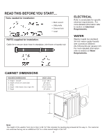
Maytag MAH2400AWW Installation Instructions - Page 7
Step 3 - pump
 |
UPC - 719881145655
View all Maytag MAH2400AWW manuals
Add to My Manuals
Save this manual to your list of manuals |
Page 7 highlights
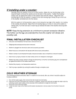
STEP 3 INSTALL THE WASHER (NOTE: Under the counter installation do not require removal of the work top. Proceed with the following instructions.) 11.. Place the drain hose in the drain facility. Be sure an airtight connection is NOT made between the drain hose and the standpipe. Standpipe must be at least 18" high. NOTE: If drain standpipe is in excess of 5 feet above floor level, a drain hose extension kit ((PPartt ##1120012646820) will need to be installed. If drain standpipe is in excess of 10 feet above floor level, a pump accessory kit (Part #12001674) may need to be installed. NOTE: Caution must always be exercised to avoid collapsing or damaging the drain hose. For best performance the drain hose should not be restricted in any way, through elbows, couplings or excessive lengths. For installations where the drain hose cannot be conveniently elevated to at least 18", the drain hose must be supported. 2. 2. fpChnwMCiwtee"anahHloenanahahsiueaeOdcdscseiseckdrhetshhTcceesitoeoc.hkeke."ftfTrni.serorDleitttlTssuhnhhfhtephO.oirreeeeagne2eeoOatthr/haNsithisn3tncnateodhheteOlhlcreoseeotnatthhTHteofftshiiehenh,blaeOehlOtdoeocyhohoTtasiVrhseuntsothenoeehmEraelsawendcenteRmtunthktoardw.oisdTnheatefTteeiCoIsorteunGHphrnhkrtsnOndaorsevOHeopsetluiLadlisonnulTTalriDleetvefer"dsEteHfaerottnafosrNhatca.Ouuhua.wteh.uMhsbgecDTawccebhefa"OiareirneatoldkeHil.ntslrsseseeNhTcdOhewntaootisOe,gThthatsnuhstrhcTeosaenrteahteirhsceesfOnnaetaeehonctidciVuhnsr2etnkibtceeEop/dCshw3eyrnefiRehOdoittsatrhoo.oeTrhLw.nahfOsIotDTdtoGnoaeahhnnhfdsteHweeemfteeteauhurTaHsaaurrdaensvEucnOcrconthakrbNhioeeTmldweelbtvt.sehfdrieeieictnnnlehirl.osusorngtna-ll 96" MAX. 18" MIN. 96" MAX. 18" MIN. 3. Turn on "HOT" and "COLD" water supply and check all connections at the water valve and the faucet for leaks. NOTE: Accessory inlet hoses are available in various lengths up to 10 feet. 4. Plug power cord into a grounded 120 volt 60 Hz approved electrical service protected by a 15-amp fuse or comparable circuit breaker. This washer is grounded through the third prong of the power cord when plugged into a three prong grounded receptacle. 5. Slide washer into position. 6. Level washer by turning the leveling legs in or out as necessary by hand. When the washer is level, tighten the leveling leg lock nuts up against the base of the washer using the wrench supplied with the washer. NOTE: The washer must be leveled on all 4 sides. A carpenter's level should be used on all 4 corners of the washer. It's a good idea after the first dozen washes to recheck the levelness of the washer. 7
-
 1
1 -
 2
2 -
 3
3 -
 4
4 -
 5
5 -
 6
6 -
 7
7 -
 8
8
 |
 |
