Maytag MED5630H Owners Manual - Page 12
Power Supply Cord Connection
 |
View all Maytag MED5630H manuals
Add to My Manuals
Save this manual to your list of manuals |
Page 12 highlights
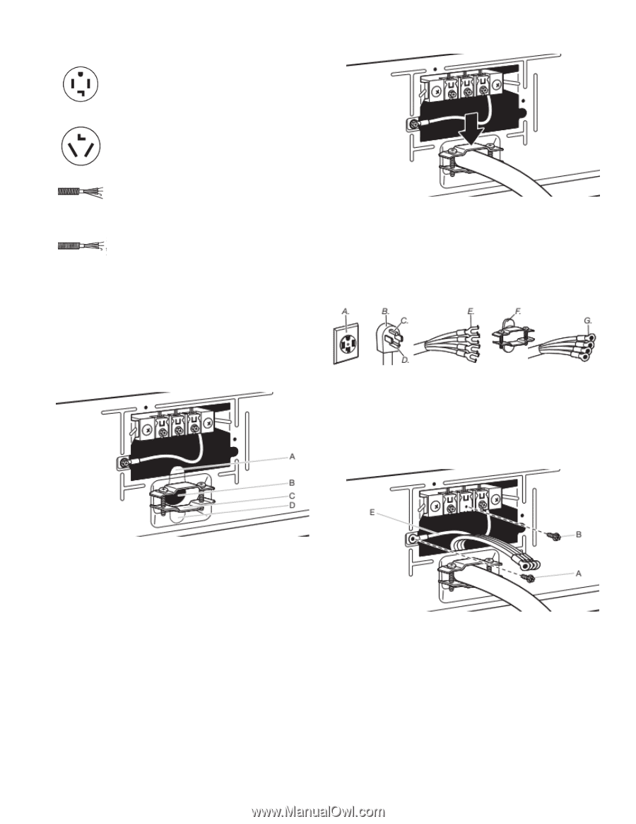
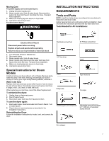
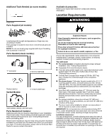
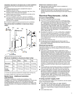
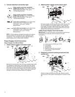
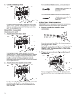
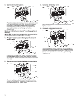
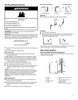
3. Choose electrical connection type Power supply cord 4-wire receptacle (NEMA Type 14-30R): Go to "4-Wire Power Supply Cord Connection." Then, go to "Venting Requirements." Power supply cord 3-wire receptacle (NEMA Type 10-30R): Go to "3-Wire Power Supply Cord Connection." Then, go to "Venting Requirements." 4-wire direct connection: Go to "Direct Wire Strain Relief," then "4-Wire Direct Wire Connection," then, go to "Venting Requirements." 3-wire direct connection: Go to "Direct Wire Strain Relief", then "3-Wire Direct Wire Connection," then, go to "Venting Requirements." NOTE: If local codes do not permit connection of a cabinetground conductor to neutral wire, go to "Optional 3-wire Connection." This connection may be used with either a power supply cord or a direct wire connection. Power Supply Cord Connection Power Supply Cord Strain Relief 1. Attach power supply cord strain relief 2. Attach power supply cord to strain relief Put power supply cord through the strain relief. Be sure that the wire insulation on the power supply cord is inside the strain relief. The strain relief should have a tight fit with the dryer cabinet and be in a horizontal position. Do not further tighten strain relief screws at this point. 4-Wire Power Supply Cord Connection IMPORTANT: A 4-wire connection is required for mobile homes and where local codes do not permit the use of 3-wire connections. A. 4-wire receptacle (NEMA type 14-30R) B. 4-prong plug C. Ground prong D. Neutral prong E. Spade terminals with upturned ends F. 3/4" (19 mm) UL-listed strain relief G. Ring terminals 3. Prepare to connect neutral ground wire and neutral wire Remove the screws from a 3/4" (19 mm) UL-listed strain relief (UL marking on strain relief). Put the tabs of the two clamp sections (C) into the hole below the terminal block opening (B) so that one tab is pointing up (A) and the other is pointing down (D), and hold in place. Tighten strain relief screws just enough to hold the two clamp sections (C) together. Remove center terminal block screw (B). Remove neutral ground wire (E) from green external ground conductor screw (A). 12
-
 1
1 -
2
-
3
-
4
-
5
-
6
-
 7
7 -
 8
8 -
 9
9 -
 10
10 -
 11
11 -
 12
12 -
 13
13 -
 14
14 -
 15
15 -
 16
16 -
 17
17 -
18
-
19
-
20
-
21
-
22
-
23
-
24
-
25
-
26
-
27
-
28
-
29
-
30
-
31
-
32
-
33
-
34
-
35
-
36
-
37
-
38
-
39
-
40
-
41
-
42
-
43
 |
 |