Maytag MEDB755DW Installation Guide - Page 16
Make Gas Connection
 |
View all Maytag MEDB755DW manuals
Add to My Manuals
Save this manual to your list of manuals |
Page 16 highlights
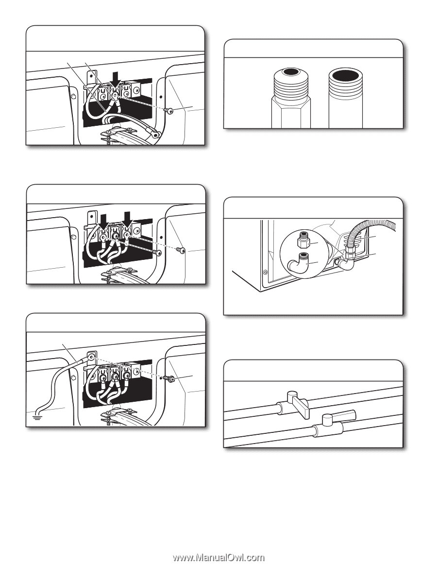
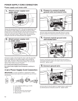
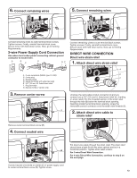
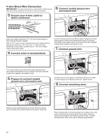
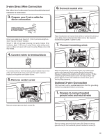
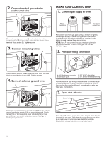
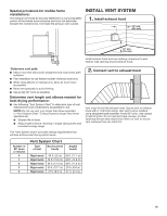
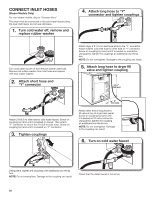
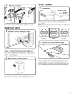
2. Connect neutral ground wire and neutral wire EC MAKE GAS CONNECTION 1. Connect gas supply to dryer Flared B maAle fitting mNoalne-fflBiattriendg Connect neutral ground wire (E) and neutral wire (white or center wire) (C) of power supply cord or cable under center terminal block screw (B). Tighten screw. 3. Connect remaining wires Remove red cap from gas pipe. Using a wrench to tighten, connect gas supply to dryer. Use pipe-joint compound on threads of all non-flared male fittings. If flexible metal tubing is used, be sure there are no kinks. NOTE: For LP gas connections, you must use pipe-joint compound resistant to action of LP gas. Do not use TEFLON® tape. 2. Plan pipe fitting connection A D B C Place hooked ends of remaining wires under outer terminal block screws (hooks facing right). Tighten screws. 4. Connect external ground wire GE A A. 3/8" flexible gas connector C. 3/8" to 3/8" pipe elbow B. 3/8" dryer pipe D. 3/8" pipe-to-flare adapter fitting A combination of pipe fittings must be used to connect dryer to existing gas line. A recommended connection is shown. Your connection may be different, according to supply line type, size, and location. 3. Open shut-off valve Closed valve Open valve Connect a separate copper ground wire (G) from the external ground conductor screw (A) to an adequate ground. Finally, reinsert tab of terminal block cover into slot of dryer rear panel. Secure cover with hold-down screw. Now, go to Venting Requirements. Open shut-off valve in supply line; valve is open when handle is parallel to gas pipe. Then, test all connections by brushing on an approved noncorrosive leak-detection solution. Bubbles will show a leak. Correct any leaks found. 16
-
 1
1 -
2
-
3
-
4
-
5
-
6
-
7
-
8
-
9
-
10
-
 11
11 -
 12
12 -
 13
13 -
 14
14 -
 15
15 -
 16
16 -
 17
17 -
 18
18 -
 19
19 -
 20
20 -
 21
21 -
22
-
23
-
24
-
25
-
26
-
27
-
28
-
29
-
30
-
31
-
32
-
33
-
34
-
35
-
36
-
37
-
38
-
39
-
40
-
41
-
42
-
43
-
44
 |
 |