Maytag MEDC400VW Installation Instructions - Page 7
wire connection: Power Supply Cord - dryer by
 |
UPC - 883049145723
View all Maytag MEDC400VW manuals
Add to My Manuals
Save this manual to your list of manuals |
Page 7 highlights
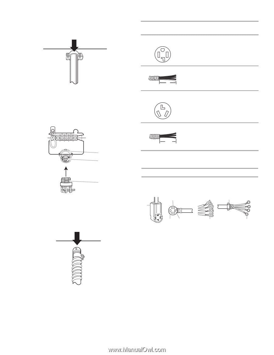
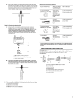
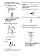
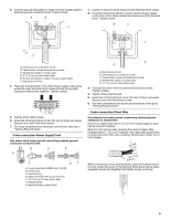
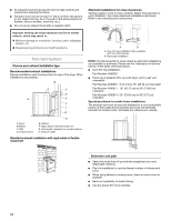
■ Put power supply cord through the strain relief. Be sure that the wire insulation on the power supply cord is inside the strain relief. The strain relief should have a tight fit with the dryer cabinet and be in a horizontal position. Do not further tighten strain relief screws at this point. Style 2: Direct wire strain relief ■ Unscrew the removable conduit connector and any screws from a ³⁄₄" (1.9 cm) UL listed strain relief (UL marking on strain relief). Put the threaded section of the strain relief through the hole below the terminal block opening. Reaching inside the terminal block opening, screw the removable conduit connector onto the strain relief threads. A B C A. Removable conduit connector B. Hole below terminal block opening C. Strain relief threads ■ Put direct wire cable through the strain relief. The strain relief should have a tight fit with the dryer cabinet and be in a horizontal position. Tighten strain relief screw against the direct wire cable. Electrical Connection Options If your home has: And you will be connecting to: Go to Section 4-wire receptacle (NEMA Type 14-30R) A UL listed, 120/240-volt minimum, 30-amp, dryer power supply cord* 4-wire connection: Power supply cord 4-wire direct 5" (12.7 cm) 3-wire receptacle (NEMA type 10-30R) A fused disconnect or circuit breaker box* A UL listed, 120/240-volt minimum, 30-amp, dryer power supply cord* 4-wire connection: Direct Wire 3-wire connection: Power supply cord 3-wire direct 3¹⁄₂" (8.9 cm) A fused disconnect or circuit breaker box* 3-wire connection: Direct Wire *If local codes do not permit the connection of a cabinet-ground conductor to the neutral wire, go to "Optional 3-wire connection" section. 4-wire connection: Power Supply Cord IMPORTANT: A 4-wire connection is required for mobile homes and where local codes do not permit the use of 3-wire connections. B F A CD E G A. 4-wire receptacle (NEMA type 14-30R) B. 4-prong plug C. Ground prong D. Neutral prong E. Spade terminals with upturned ends F. ¾" (1.9 cm) UL listed strain relief G. Ring terminals 4. Now complete installation following instructions for your type of electrical connection: 4-wire (recommended) 3-wire (if 4-wire is not available) 7
-
 1
1 -
 2
2 -
 3
3 -
 4
4 -
 5
5 -
 6
6 -
 7
7 -
 8
8 -
 9
9 -
 10
10 -
 11
11 -
 12
12 -
13
-
14
-
15
-
16
-
17
-
18
-
19
-
20
-
21
-
22
-
23
-
24
 |
 |