Maytag MER4351AAB Installation Manual
Maytag MER4351AAB Manual
 |
View all Maytag MER4351AAB manuals
Add to My Manuals
Save this manual to your list of manuals |
Maytag MER4351AAB manual content summary:
- Maytag MER4351AAB | Installation Manual - Page 1
INSTRUCTIONS WITH THE APPLIANCE INSTALLATION MANUAL Electric 30-inch Wide Free-standing Range PLEASE KEEP THIS MANUAL FOR FUTURE REFERENCE THE MANUAL IS INTENDED TO ASSIST IN THE INITIAL INSTALLATION AND ADJUSTMENTS OF THE RANGE. SPECIAL WARNING Only qualified personnel should install or service - Maytag MER4351AAB | Installation Manual - Page 2
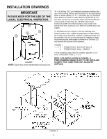
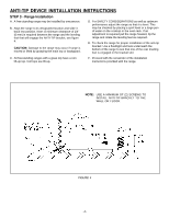
located above the surface units should be avoided. If cabinet storage is to be provided, the risk can be reduced by installing a range hood that projects horizontally a minimum of 5 inches (13 cm) beyond the bottom of the cabinets. FIGURE 1 1, 2, 3 - COMBUSTIBLE BUILDING WALLS. 4 - COMBUSTIBLE WALL - Maytag MER4351AAB | Installation Manual - Page 3
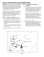
of range tip-over exists if the appliance is not installed in accordance with the provided installation instructions. The proper use of this device minimizes the risk of TIP-OVER. In using this device the consumer must still observe the safety precautions as stated in the USE and CARE MANUAL and - Maytag MER4351AAB | Installation Manual - Page 4
rear leveling feet is engaged in the bracket slot. C. All freestanding ranges with a glass top have a non lift-up top. Coil tops are lift-up. F. Proceed with the remainder of the installation instructions provided with the range. NOTE: USE A MINIMUM OF (2) SCREWS TO INSTALL ANTI-TIP BRACKET TO - Maytag MER4351AAB | Installation Manual - Page 5
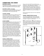
pronged plug at the opposite end. RANGE CONNECTIONS Some models are shipped direct from the factory with service cords (pigtails) attached. There are no range connections necessary on these models. Just plug into the range outlet. On models not provided with a service cord, connection to the power - Maytag MER4351AAB | Installation Manual - Page 6
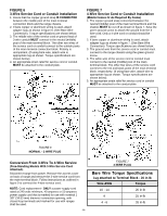
WIRE PLUG Conversion From 3-Wire To 4-Wire Service (Free-Standing Models With 3-Wire Service Cord Attached). Disconnect range from power. Remove the access cover on back of range and remove the 3-wire service cord from the main terminal block. Follow instructions as outlined in figure 9 to connect - Maytag MER4351AAB | Installation Manual - Page 7
de 30 pulgadas (76.2 cm) de ancho CONSERVE ESTE MANUAL PARA REFERENCIA FUTURA EL MANUAL TIENE LA FINALIDAD DE AYUDARLE EN LA INSTALACIÓN Y AJUSTES Título 24 CFR, Parte 3280 (anteriormente Federal Standard for Mobile Home Construction and Safety, Título 24 HUD, Parte 280)) o, cuando dichas - Maytag MER4351AAB | Installation Manual - Page 8
= 30² (76.2 CM) - 31² (78.7 CM) EN CANADÁ "B" = 7² (17.8 CM) - 7 1/2² (19.1 CM) EN CANADÁ "B" 16² (40.6 CM) 36² (91.5 CM) ALTURA A LA PARTE SUPERIOR DEL MOSTRADOR 5 3/4² (14.6 CM) "A" ABERTURAS DEL GABINETE DE ARRIBA Y DE ABAJO PROVEA UN TOMACORRIENTE DE 120/208, 120/240 VOLTIOS POR CORDÓN EL - Maytag MER4351AAB | Installation Manual - Page 9
reduce el riesgo de LADEO. Al usar este dispositivo el consumidor aun debe acatar las precauciones de seguridad que se dictan en el MANUAL DE USO Y CUIDADO y debe evitar utilizar las puertas del horno como banquillo. Las instrucciones de instalación se proporcionan para madera y cemento tanto en - Maytag MER4351AAB | Installation Manual - Page 10
según sea necesario. E. Para revisar que el soporte antiladeo esté instalado correctamente en la estufa: Use una linterna y vea debajo de la parte inferior de la estufa para comprobar que una de las patas niveladoras posteriores esté asegurada a la ranura del soporte. F. Continúe con el resto - Maytag MER4351AAB | Installation Manual - Page 11
úrese de que estén bien aseguradas las conexiones eléctricas y coloque las cubiertas de nuevo. Quite la cubierta de acceso del bloque terminal de la parte posterior de la estufa. (Vea la figura 5). CONEXIONES DE LA ESTUFA (en Canadá) Este modelo se embarcó directamente de fábrica con el cordón de - Maytag MER4351AAB | Installation Manual - Page 12
independientes que tengan sujeto un cordón de servicio de 3 hilos). Desconecte la estufa del suministro eléctrico. Retire la cubierta de acceso de la parte posterior de la estufa y quite el cordón de servicio de 3 hilos del bloque principal del terminal. Siga las instrucciones según se indican en la - Maytag MER4351AAB | Installation Manual - Page 13
INSTRUCTIONS AVEC L'APPAREIL MANUEL DE MISE EN SERVICE Cuisinière électrique amovible de 30 po (76,2 cm) VEUILLEZ CONSERVER CE MANUEL POUR RÉFÉRENCE ULTÉRIEURE CE MANUEL EST DESTINÉ À FACILITER LA MISE EN SERVICE ère est adjacente à des armoires pouvant supporter une température inférieure à 194°F - Maytag MER4351AAB | Installation Manual - Page 14
amovible peut être directement contre (0 cm/po) les parois 1, 2, 3 même si celles-ci sont en matériau combustible. REMARQUE : DANS LE CAS D'UNE MISE EN SERVICE AU CANADA, UNE CUISINIÈRE AMOVIBLE NE DOIT PAS ÊTRE PLACÉE À MOINS DE 12 MM DE TOUTE SURFACE ADJACENTE. "A" = 76,2 CM (30 PO - 78,7 (31 - Maytag MER4351AAB | Installation Manual - Page 15
cuisinière risque de basculer si elle n'est pas mise en place conformément aux instructions fournies. Si le support est utilisé correctement, il réduit le risque que la cuisinière ne BASCULE. Même si le support est utilisé correctement, le consommateur doit observer les précautions indiquées dans le - Maytag MER4351AAB | Installation Manual - Page 16
ère à l'aide d'une lampe électrique et vérifier que l'un des pieds arrière de mise à niveau est bien inséré dans la fente du support. F. Finir la mise en service de la cuisinière tel qu'indiqué dans les instructions fournies avec la cuisinière. REMARQUE : UTILISER AU MOINS 2 VIS POUR LA FIXATION DU - Maytag MER4351AAB | Installation Manual - Page 17
la puissance raccordée totale (en kW). ALIMENTATION ÉLECTRIQUE (Canada) Lors de la mise en service, la cuisinière doit être installée conformément aux normes ACN STD.C22.1 de l'édition la quatre fils peuvent être utilisés avec les circuits de PLAQUE SUPPORT DE GAINE COUVERCLE D'ACCÈS FIGURE 5 -17- - Maytag MER4351AAB | Installation Manual - Page 18
déconnecter le cordon d'alimentation à 3 fils du bornier. Suivre les instructions données à la figure 9 pour connecter le cordon à 4 fils PAS ENCASTRÉE ESTAMPÉ "CORD" (CORDON) POUR L'USAGE AVEC UNE GAINE, ENLEVEZ LE SUPPORT, RENVERSEZ-LE ET RATTACHEZ-LE AVEC LE TROU MARQUÉ "CONDUIT" VERS LE BAS.
-
 1
1 -
 2
2 -
 3
3 -
 4
4 -
 5
5 -
 6
6 -
 7
7 -
8
-
9
-
10
-
11
-
12
-
13
-
14
-
15
-
16
-
17
-
18
 |
 |
INSTALLER
: LEAVE THESE INSTRUCTIONS WITH THE APPLIANCE
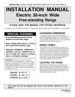
INSTALLATION MANUAL
Electric 30-inch Wide
Free-standing Range
PLEASE KEEP THIS MANUAL FOR FUTURE REFERENCE
THE MANUAL IS INTENDED TO ASSIST IN THE INITIAL INSTALLATION AND ADJUSTMENTS OF THE RANGE.
SPECIAL WARNING
Only qualified personnel should
install or service this range.
Read °Safety Instructions± in Use &
Care book before using range.
Improper installation, adjustment,
alteration, service, maintenance or
use of range can result in serious
injury or property damage.
CLEARANCE
DIMENSIONS
For complete information in regard to installation of
freestanding range, see figures 1 and 2 on page 2. For
SAFETY CONSIDERATIONS do not install a range in
any combustible cabinetry which is not in accord with the
installation clearances shown in figure 1.
MOBILE
HOMES
The installation of a range designed for mobile home
installation must conform with the Manufactured Home
Construction and Safety Standard, Title 24 CFR, Part
3280 (formerly the Federal Standard for Mobile Home
Construction and Safety, Title 24 HUD, Part 280) or,
when such standard is not applicable, the Standard for
Manufactured Home Installations 1982 (Manufactured
Home Sites, Communities and Set-Ups), ANSI
A225.1-latest edition, or with local codes.
LOCATING THE
RANGE
Place range in a well lit area. Do not set range over
holes in the floor or other locations where it may be
subject to strong drafts. Any opening in the wall behind
the range and in the floor under the range should be
sealed. Make sure the flow of cooling/ventilation air is
not obstructed below the range.
CAUTION:
This range has been designed in
accordance with the requirements of various safety
agencies and complies with the maximum allowable
wood cabinet temperatures of 194
±
F. If this range is
installed with cabinets that have a lower working
temperature than 194
±
F, discoloration, delamination
or melting may occur.
8101P556-60
(06-03-00)
Your range may not be equipped with some of the features referred to in this
manual.
ENGLISH
’
PP. 1-6
ESPA²OL
’
pÆg. 7-12
FRAN˙AIS
’
p. 13-18