Maytag MGDB765FW W10240504 - Page 14
GAS DRYER U.S. and Canadian Installations
 |
View all Maytag MGDB765FW manuals
Add to My Manuals
Save this manual to your list of manuals |
Page 14 highlights
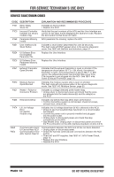
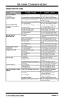
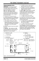
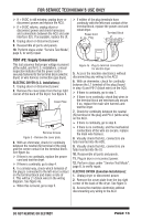
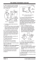
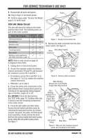
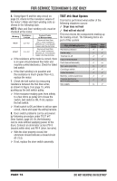
FOR SERVICE TECHNICIAN'S USE ONLY 4. With an ohmmeter, check the continuity from L1 and N plug terminals of the power cord to the terminals for L1 and N on the ACU. See figure 4b. Power Cord Plug N Neu L1 ACU P9 L1 1 Wire Harness Power Cord Figure 5 - Power cord-to-wire harness connection for gas dryer. P/N XXXXXX Rev X XXXX-XXX MADE IN COO Date Code YDDD-xx 5 N Neu COM 1 P8 Figure 4b - Plug-to-terminal connections for electric dryer. If continuity exists for both connections, go to step 6. If an open circuit is found, check the integrity of the connections of the power cord to the harness in the dryer; harness to the ACU; and the integrity of the power cord itself. 5. If it is necessary to replace the power cord, remove the retaining clip that secures the cord to the back panel. Disconnect the cord from the main harness and the ground wire from the rear panel, then pull out the power cord. 6. Visually check that ALL connectors are fully inserted into the ACU. 7. Visually check that ALL connectors are fully inserted into the UI. 8. Reassemble all parts and panels. 9. Plug in dryer or reconnect power. 10. Perform steps under "Service Test Mode", page 6, to verify repair. GAS DRYER (U.S. and Canadian Installations): 1. Unplug dryer or disconnect power. 2. Remove the cover plate from the top right corner of the back of the dryer. See figure 3. 3. Check that the power cord is firmly connected to the dryer's wire harness. See figure 5. 4. Access the machine electronics without disconnecting any wiring to the ACU. 5. With an ohmmeter, check for continuity between the neutral (N) terminal of the plug and P8-3 (white wire) on the ACU. The left-hand side of figure 6 shows the position of the neutral terminal (N) on the power cord plug. Also see figure 2, page 12. If there is continuity, go to step 6. If there is no continuity, disconnect the white wire of the main harness from the power cord at the location illustrated in figure 5. Test the continuity of the power cord neutral wire as illustrated in figure 6. If an open circuit is found, replace the power cord. Otherwise, go to step 6. N Neu L1 COM L1 G Masse Power Cord Plug N Neu G Masse Figure 6 - Power cord terminals, gas dryer. 6. In a similar way, check for continuity between the L1 terminal of the plug and P9-2 (black wire) on the ACU. If there is continuity, go to step 7. If there is no continuity, check the continuity of the power cord in a similar way to that illustrated in figure 6, but for power cord's L1 wire. If an open circuit is found, replace the power cord. Otherwise, replace the main harness. 7. Visually check that ALL connectors are fully inserted into the ACU. 8. Visually check that ALL connectors are fully inserted into the UI. PAGE 14 DO NOT REMOVE OR DESTROY
-
 1
1 -
2
-
3
-
4
-
5
-
6
-
7
-
8
-
 9
9 -
 10
10 -
 11
11 -
 12
12 -
 13
13 -
 14
14 -
 15
15 -
 16
16 -
 17
17 -
 18
18 -
 19
19 -
20
-
21
-
22
-
23
-
24
-
25
-
26
-
27
-
28
-
29
-
30
-
31
-
32
-
33
-
34
-
35
-
36
-
37
-
38
-
39
-
40
-
41
-
42
-
43
-
44
-
45
-
46
-
47
-
48
-
49
-
50
-
51
-
52
-
53
-
54
-
55
-
56
 |
 |
