Maytag MGDB765FW W10240504 - Page 19
Temperature Levels Incorrect, Timed Dry, TIMED DRY, ALL DRYERS
 |
View all Maytag MGDB765FW manuals
Add to My Manuals
Save this manual to your list of manuals |
Page 19 highlights
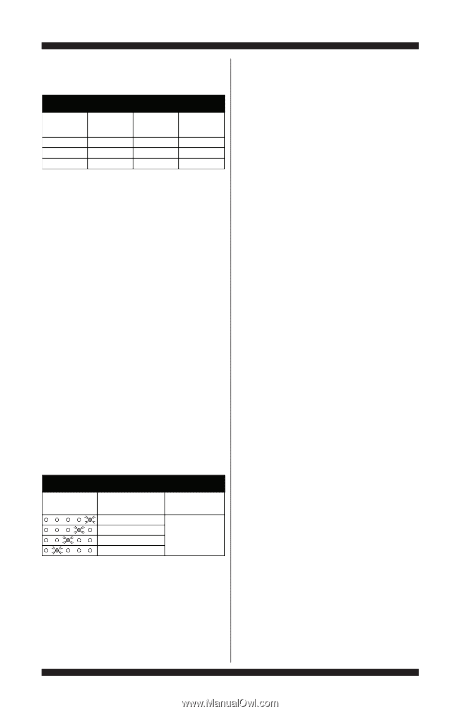
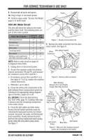
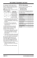
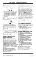
FOR SERVICE TECHNICIAN'S USE ONLY NOTE: All thermistor resistance measurements must be made while dryer is unplugged and connector removed from ACU. OUTLET THERMISTOR RESISTANCE TEMP. °F (°C) 50° (10°) 60° (16°) 70° (21°) RES. RANGE k ohms 19.0-22.0 14.8-16.8 11.5-13.5 TEMP. °F (°C) 80° (27°) 90° (32°) 100° (38°) RES. RANGE k ohms 8.5-10.5 6.8-8.8 5.0-7.0 If the resistance is OK, the outlet thermistor is good. Proceed to step 4. If the thermistor resistance does not agree with the table, replace the outlet thermistor. 4. Check P14-3 and P14-6 to dryer cabinet ground. If either pin indicates continuity to ground (short), replace wiring harness; otherwise, proceed to step 5. 5. If the preceding steps did not correct the problem, replace the ACU. Temperature Levels Incorrect - If no error code is displayed and the connections to the thermistor are good, check the exhaust temperature value at any or all of the temperature levels in question, using the Timed Dry cycle. 1. Remove load from dryer and disconnect external vent. 2. Plug in dryer or reconnect power. 3. Run a TIMED DRY cycle of at least 2 minutes in duration and select a temperature setting using heat. 4. Using a calibrated temperature probe, take a temperature measurement in the center of the exhaust outlet. The correct exhaust temperatures are as follows: EXHAUST TEMPERATURES TEMPERATURE SETTING (appearance may vary) HEAT TURNS OFF* °F (°C) HEAT TURNS ON °F (°C) 155° ± 5° (68° ± 3°) 140° ± 5° (60° ± 3°) 125° ± 5° (52° ± 3°) 105° ± 5° (41° ± 3°) 10-15° (6-8°) below the heat turn off temperature If the temperature is not reached within ~7 minutes, check voltage level and vent blockage, and then retest. If the temperature probe does not agree with temperature setting, replace the outlet thermistor. If the temperature probe confirms the temperature setting, retest at a different temperature setting. 5. If the preceding steps did not correct the problem, replace the ACU. TEST #4b: Thermal Fuse The thermal fuse is wired in series with the dryer drive motor. 1. Unplug dryer or disconnect power. 2. Access the thermal fuse by removing the toe panel. For thermal fuse location, see figure 10a or 10b, page 17. 3. Using an ohmmeter, check the continuity across the thermal fuse. If the ohmmeter indicates an open circuit, replace the thermal fuse. TEST #4c: Thermal Cut-Off If the dryer does not produce heat, check the status of the thermal cut-off. 1. Unplug dryer or disconnect power. 2. Access the thermal cut-off by removing the toe panel. For thermal cut-off location, see figure 10a or 10b. 3. Using an ohmmeter, check the continuity across the thermal cut-off. See figures 10a and 10b, page 17, for location. 4. If the ohmmeter indicates an open circuit, perform the following: ALL DRYERS: Replace both the thermal cut-off and high limit thermostat. In addition, check for blocked or improper exhaust system, and, on electric dryers, for heat element malfunction. TEST #4d: Gas Valve (Gas Dryer) 1. Unplug dryer or disconnect power. 2. Access the gas valve by removing the toe panel. DO NOT REMOVE OR DESTROY PAGE 19
-
 1
1 -
2
-
3
-
4
-
5
-
6
-
7
-
8
-
9
-
10
-
11
-
12
-
13
-
 14
14 -
 15
15 -
 16
16 -
 17
17 -
 18
18 -
 19
19 -
 20
20 -
 21
21 -
 22
22 -
 23
23 -
 24
24 -
25
-
26
-
27
-
28
-
29
-
30
-
31
-
32
-
33
-
34
-
35
-
36
-
37
-
38
-
39
-
40
-
41
-
42
-
43
-
44
-
45
-
46
-
47
-
48
-
49
-
50
-
51
-
52
-
53
-
54
-
55
-
56
 |
 |