Maytag MGR7775 Installation Instructions - Page 10
¢As¢, BK:sc.Het - white
 |
UPC - 883049187068
View all Maytag MGR7775 manuals
Add to My Manuals
Save this manual to your list of manuals |
Page 10 highlights
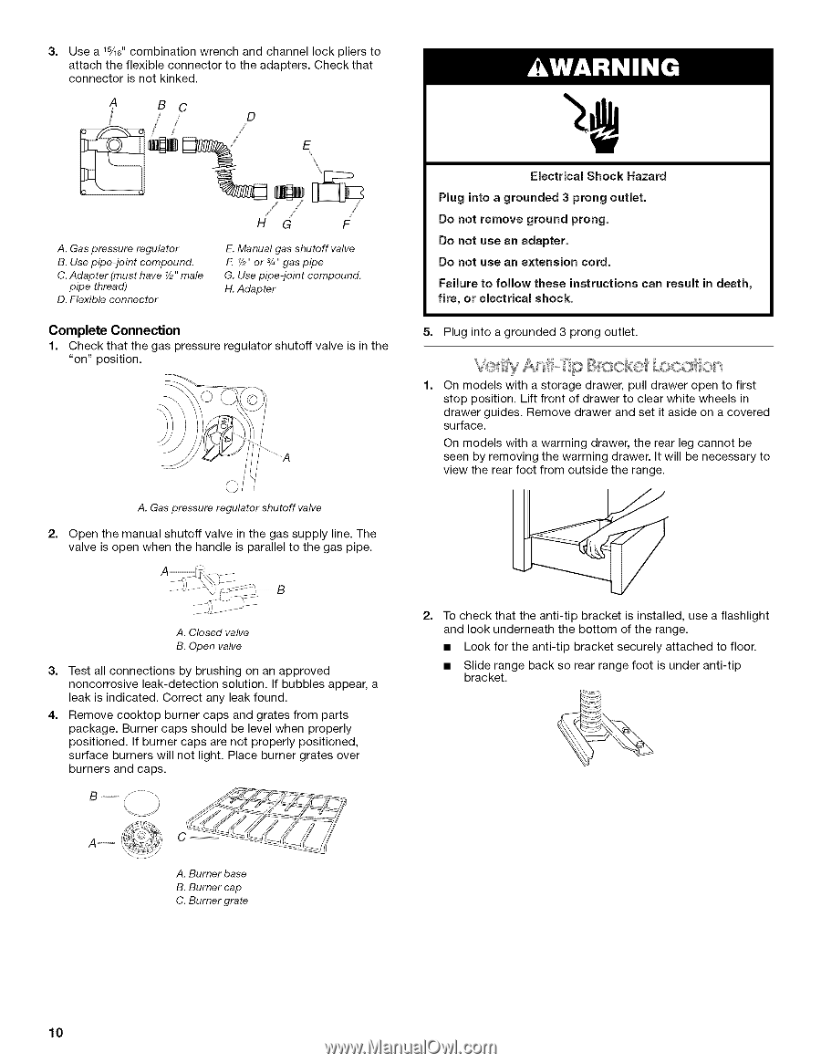
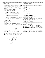
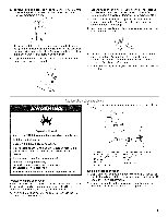
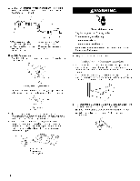
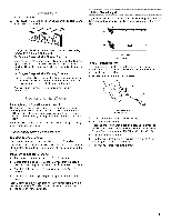
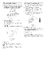
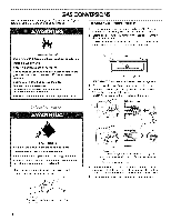
3= Use a 1%e"combination wrench and channel lock pliers to attach the flexible connector to the adapters. Check that connector is not kinked. A BC t/ D A. Gas pressure regulator B. Use pipe-joint compound. C. Adapter (must have Y2"male pipe thread) D. Flexible connector HG F E. Manual gas shutoff valve F V2" or 3/4"gas pipe G. Use pipe-joint compound. H. Adapter Complete Connection 1. Check that the gas pressure regulator shutoff valve is in the "on" position. A. Gaspressure regulator shutoff valve 2. Open the manual shutoff valve in the gas supply line. The valve is open when the handle is parallel to the gas pipe. Electrical Shock Hazard Plug into a grounded 3 prong outlet. Do not remove ground prong. Do not use an adapter. Do not use an extension cord. Failure to follow these instructions can result in death, fire, or electrical shock. 5. Plug into a grounded 3 prong outlet. '¢As¢y' A/' p BK:sc.Het o 1. On models with a storage drawer, pull drawer open to first stop position. Lift front of drawer to clear white wheels in drawer guides. Remove drawer and set it aside on a covered surface. On models with a warming drawer, the rear leg cannot be seen by removing the warming drawer. It will be necessary to view the rear foot from outside the range. A. Closed valve B. Open valve 3= Test all connections by brushing on an approved noncorrosive leak-detection solution. If bubbles appear, a leak is indicated. Correct any leak found. 4. Remove cooktop burner caps and grates from parts package. Burner caps should be level when properly positioned. If burner caps are not properly positioned, surface burners will not light. Place burner grates over burners and caps. 2= To check that the anti-tip bracket is installed, use a flashlight and look underneath the bottom of the range. • Look for the anti-tip bracket securely attached to floor. • Slide range back so rear range foot is under anti-tip bracket. A-- A. Burner base B. Burner cap C. Burner grate 10
-
 1
1 -
2
-
3
-
4
-
 5
5 -
 6
6 -
 7
7 -
 8
8 -
 9
9 -
 10
10 -
 11
11 -
 12
12 -
 13
13 -
 14
14 -
 15
15 -
16
-
17
-
18
-
19
-
20
 |
 |