Maytag MGR7775 Installation Instructions - Page 17
NOTE: Refer to the Model Number
 |
UPC - 883049187068
View all Maytag MGR7775 manuals
Add to My Manuals
Save this manual to your list of manuals |
Page 17 highlights
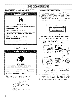
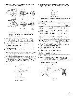
4. Turn gas pressure regulator cap counterclockwise with a 5/8"combination wrench to remove. NOTE: Do not remove the spring beneath the cap. Side view before 4= Gas orifice spuds are stamped with a number on the side. Replace the LP gas orifice spud with the correct Natural gas orifice spud. B / C Side view after A. Plastic cover B. Gas pressure regulator cap with hollow end facing out C. Gas pressure regulator cap with sofid end facing out D. Washer E. Gas pressure regulator cap 5. Turn over the gas pressure regulator cap and reinstall on regulator so that the solid end faces out and the marking "
-
 1
1 -
2
-
3
-
4
-
5
-
6
-
7
-
8
-
9
-
10
-
11
-
 12
12 -
 13
13 -
 14
14 -
 15
15 -
 16
16 -
 17
17 -
 18
18 -
 19
19 -
 20
20
 |
 |
4.
Turn gas pressure
regulator
cap counterclockwise
with
a
5/8"combination
wrench
to remove.
NOTE: Do not remove the spring
beneath
the cap.
B
C
Side
view
before
/
Side
view
after
A. Plastic
cover
B. Gas pressure
regulator
cap with hollow
end facing out
C. Gas pressure
regulator
cap with sofid end facing
out
D. Washer
E. Gas pressure
regulator
cap
5.
Turn over the gas pressure
regulator
cap and reinstall on
regulator
so that the solid end faces out and the marking
"<- N" is facing the direction
shown
in the above drawing.
6.
Replace
plastic cover over gas pressure
regulator
cap.
To
Convert
Surface
Burners
1.
Remove
burner cap.
or Quadrex
screwdriver,
remove the burner
2.
Using a Phillips
®
base.
NOTE: Reinstall one of the screws
through
the range cooktop
to hold the orifice spud holder in place while removing
and
replacing
the orifice spuds.
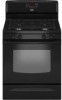
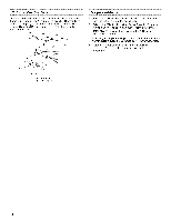
3.
Apply masking
tape to the end of a sAe"nut driver to help hold
the gas orifice spud in the nut driver while changing
it. Press
nut driver
down onto the gas orifice spud and remove
by
turning
it counterclockwise
and lifting out. Set gas orifice
spud aside.
A
D
4=
Gas orifice spuds
are stamped
with
a number
on the side.
Replace the LP gas orifice spud with the correct
Natural gas
orifice spud.
A. Stamped
number
Refer to the following
chart for the correct
Natural gas orifice
spud placement.
Natural
Gas Orifice
Spud Chart
Burner
Rating
Color
Size
ID
Number
17,000 BTU
Red/Magenta
2.10 mm
N210
15,500 BTU
Red/Black
2.00 mm
N200
14,200 BTU
Red/Orange
1.90 mm
N190
13,000/13,500
BTU
Red/Blue
1.85 mm
N185
12,000/12,500
BTU
Red/Yellow
1.80 mm
N180
9,500 BTU
Red/Brown
1.55 mm
N155
8,000 BTU
Red/White
1.40 mm
N140
5,000 BTU
Red/Brass
1.10 mm
Nl10
NOTE: Refer to the Model Number
and Serial Number Plate
located
behind the left side of the storage
or warming
drawer for
proper
sizing of spuds
for each burner
location.
5.
Place LP gas orifice spuds
in plastic
parts bag for future use
and keep with package
containing
literature.
6.
Replace the burner base using
both screws.
7.
Replace
burner cap.
8.
Repeat steps
1-7 for the remaining
burners.
To Convert
Oven
Bake
Burner
1.
Remove
oven racks.
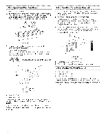
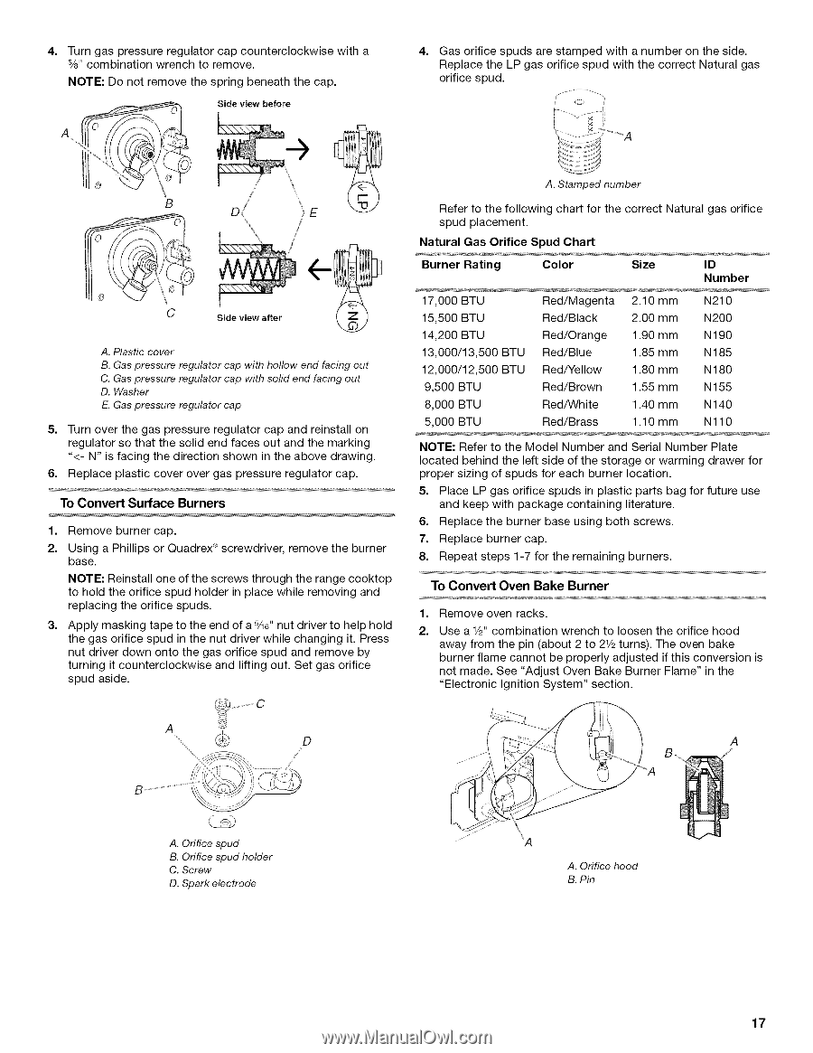
2.
Use a 1/2" combination
wrench to loosen the orifice hood
away from the pin (about 2 to 21/2turns). The oven bake
burner
flame cannot
be properly
adjusted
if this conversion
is
not made. See "Adjust
Oven Bake Burner Flame"
in the
"Electronic
Ignition System"
section.
A. Orifice spud
B. Orifice spud holder
C. Screw
D. Spark electrode
A. Orifice hood
B. Pin
17