McAfee IIP-M65K-ISAA Quick Start Guide - Page 1
McAfee IIP-M65K-ISAA - Network Security Platform M-6050 Manual
 |
View all McAfee IIP-M65K-ISAA manuals
Add to My Manuals
Save this manual to your list of manuals |
Page 1 highlights
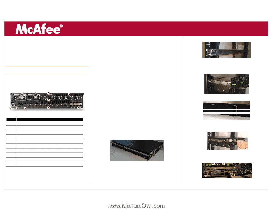
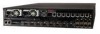
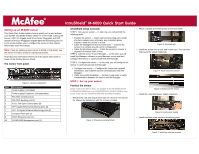
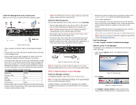
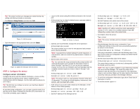
IntruShield® M-6050 Quick Start Guide Setting up an M-6050 sensor This Quick Start Guide explains how to quickly set up and activate your McAfee IntruShield M-6050 sensor in in-line mode. Cabling the sensor's XFP (10 Gigabit Small Form-factor Pluggable) and SFP (Small Form-factor Pluggable) Gigabit Ethernet Monitoring ports for in-line mode enables you to configure the sensor to drop attacks before they reach their target. Note: If you are setting up your sensor in SPAN or Tap mode, see the sensor's Product Guide for cabling instructions. All product documentation referenced in this Quick Start Guide is found on the McAfee Service Portal. The sensor front panel Item 1 2 3 4 5 6 7 8 9 10 Figure 1: Sensor components Description Power supply A (included) Power supply B (optional; sold separately) RS-232C Control port (1) RS-232C Auxiliary port (1) RJ-11 Fail-Open Control ports (8) SFP Gigabit Ethernet Monitoring ports (8) XFP 10 Gigabit Ethernet Monitoring ports (8) Compact Flash port (1) RJ-45 Response port (1) 10/100/1000 Management port (1) IntruShield setup overview STEP 1: Set up your sensor - In step one, you will perform the following tasks. Position the sensor - Attach rails and mounting ears; install interface modules and, optionally, any redundant power supplies; install the sensor in a rack. Cable the Management and Console ports - Connect the sensor to a console you will use for configuration. Cable the Monitoring ports - Cable the sensor to monitor a segment of network traffic in-line. STEP 2: Add the sensor to your Manager - In this step, you will install the Manager software on your Manager server and then configure the sensor to communicate with the Manager. STEP 3: Configure the sensor - In this step, you will configure the sensor to communicate with the Manager. Configure the sensor - Configure the sensor with network information, and establish secure communication with the Manager. Verify successful installation - Perform some tasks to verify communication between the sensor and the Manager. STEP 1: Set up your sensor Position the sensor Details on all of the tasks in Step 1 are available in the IntruShield Sensor Configuration Guides and in the IntruShield Sensor Product Guide for your sensor model. Also see IntruShield Slide Rail Assembly Procedure. 1. Release the rails and attach inner rails (of a three-in-one set) to the chassis by fastening it with the screws provided. Figure 2: Chassis-to-rail attachment 2. Attach L-shape and external rails to the rack frame. Figure 3: Mounted rails 3. Install the sensor into a rack and mount ears. You can also mid-mount the sensor (optional). Figure 4: Rack-mount the sensor Figure 5: Mid-mount the sensor 4. Install the redundant power supply (optional). Figure 6: Insert power supply 5. Install modules in the sensor's Monitoring ports. Figure 7: Install the interface module
-
 1
1 -
 2
2 -
 3
3 -
 4
4
 |
 |