McAfee IIP-M65K-ISAA Quick Start Guide - Page 2
in-line mode, Start > Programs > IntruShield > IntruShield Security Manager, Login ID,
 |
View all McAfee IIP-M65K-ISAA manuals
Add to My Manuals
Save this manual to your list of manuals |
Page 2 highlights
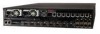
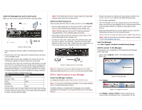
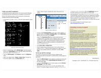
Cable the Management and Console ports Make sure the sensor is powered OFF before attaching cables. Figure 8: Sensor setup 1. Plug a Category 5e Ethernet cable in the Management (Mgmt) port. 2. Plug the other end of the cable into the network device connected to your Manager server. 3. Plug the DB9 Console cable supplied in the sensor box into the Console port (labeled Console on the sensor front panel). 4. Connect the other end of the Console port cable directly to a COM port of the PC or terminal server you will be using to configure the sensor (for example, a PC running correctly configured Windows Hyperterminal software). You must connect directly to the console for initial configuration; you cannot configure the sensor remotely. The required settings for HyperTerminal are: Name Setting Baud rate 38400 Number of Bits 8 Parity None Stop Bits 1 Control Flow None 5. Plug the female end of a power cable into the power inlet and plug the other end into a power source. The sensor ships with standard US power and international cables. Note: The M-6050 does not have a power switch; you need only plug the power cable into a power source. Cable the Monitoring ports This procedure describes how to cable a sensor to run in in-line mode. 1. Plug the cable appropriate for use with your XFP or SFP module into one of the Monitoring ports labeled xA (for example, 1A). Note: McAfee supports only those SFP modules purchased through McAfee or from a McAfee-approved vendor. 2. Plug another cable into the peer of the port used in Step 1. This port will be labeled xB (for example, 1B). 3. Connect the other end of each cable to the network devices that you want to monitor. (For example, if you plan to monitor traffic between a switch and a router, connect the cable connected to 1A to the router and the one connected to 1B to the switch.) Figure 9: Cable sensor for in-line mode Note: For instructions on how to cable the sensor to run in other operating modes, see the Sensor Product Guide for your sensor model. STEP 2: Add the sensor to your Manager Install the Manager software For detailed instructions, refer to the Manager Installation Guide. Note: You must have Administrator privileges on the target Windows server to install the Manager software. A MySQL database is included with the Manager and is installed (embedded) automatically on your target Windows server during this process. 1. Prepare the system according to the requirements outlined in the Manager Installation Guide and the IntruShield Release Notes. 2. Close all open applications. 3. Insert the Manager CD into the appropriate drive of the Windows server you will use as your Manager server. Follow the instructions in the Installation Wizard as it guides you through the entire process. 4. Obtain your Manager license via your Support account. Copy the IntruShieldLicense.jar file to the following location: installDrive:>installDirectory\IntruShield\config Note: If you do not have your license file, request one by sending e-mail to [email protected]. Start the Manager Click Start > Programs > IntruShield > IntruShield Security Manager. Add the sensor to the Manager The Manager starts, displaying the IntruShield Security Manager (ISM) Login page. 1. Log in. Default Login ID is admin; the default password is admin123. 2. Click Configure. Figure 10: Manager login Figure 11: Configure the sensor 3. Click Manager > Licenses > M-Series to select and import the IntruShieldLicense_.jar file.
-
 1
1 -
 2
2 -
 3
3 -
 4
4
 |
 |
