Milwaukee Tool M18 FUEL 1/2" HTIW & 3/8" MTIW Automotive Combo Kit Operators M - Page 3
-sawdust
 |
View all Milwaukee Tool M18 FUEL 1/2" HTIW & 3/8" MTIW Automotive Combo Kit manuals
Add to My Manuals
Save this manual to your list of manuals |
Page 3 highlights
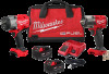
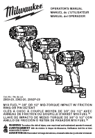
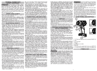
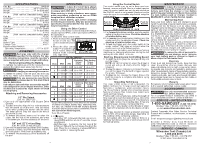
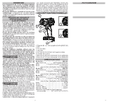
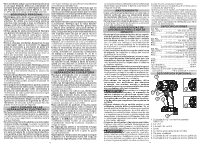
SPECIFICATIONS Cat. No 2960-20 Anvil Type 3/8" Friction Ring Weight 3.4 lbs (tool only) Weight 6.8 lbs (With heaviest compatible battery pack) Cat. No 2962-20 Anvil Type 1/2" Friction Ring Weight 3.5 lbs (tool only) Weight 6.9 lbs (With heaviest compatible battery pack) Cat. No 2962P-20 Anvil Type 1/2" Pin Detent Weight 3.5 lbs (tool only) Weight 6.9 lbs (With heaviest compatible battery pack) Volts 18 DC RPM 0 - 2575 IPM 0 - 3100 Battery Type M18™ Charger Type M18™ Recommended Ambient Operating Temperature 0°F to 125°F ASSEMBLY WARNING Recharge only with the specified for the battery. charger For spe- cific charging instructions, read the operator's manual supplied with your charger and battery. Removing/Inserting the Battery To remove the battery, push in the release buttons and pull the battery pack away from the tool. WARNING Always remove battery pack before changing or removing accessories. To insert the battery, slide the pack into the body of the tool. Make sure it latches securely into place. WARNING Only use accessories recommended for this specifically tool. Others may be hazardous. Use only sockets and other accessories specifically designed for use on impact wrenches. Other sockets and accessories might shatter or break causing injury. Attaching and Removing Accessories 1/2" Pin Detent (Cat. No. 2962P-20) 1. Use only the appropriate size Square Drive Sockets. 2. To attach a socket, align the hole in the accessory with the detent pin on the anvil. Hold the detent pin in while pushing the socket onto the anvil. The detent pin will snap into place in the hole to secure the socket. 3. To remove the socket, insert a nail or other thin object into the hole in the accessory and press in the detent pin. Pull the accessory off the anvil. 3/8" and 1/2" Friction Ring (Cat. No. 2960-20 and 2962-20) 1. Use only the appropriate size Square Drive Sockets. 2. To attach a socket, align the accessory with the anvil and push it firmly over the retaining ring. 3. To remove the accessory, pull the accessory off the anvil. OPERATION WARNING To reduce the risk of injury, always wear proper eye protection marked to comply with ANSI Z87.1. When working in dusty situations, wear appro- priate respiratory protection or use an OSHA compliant dust extraction solution. Always remove battery pack before changing or removing accessories. Only use accessories specifically recommended for this tool. Others may be hazardous. Using the Drive Control The drive control button is used to adjust the torque, rotation speed (RPM), and impact speed (IPM) for the application. To select the drive control mode: 1. Pull and release the trigger to turn on the tool. The Drive Control Button current mode indicator is lit. 2. Press the drive control button to cycle through the 4 modes. When the desired mode indicator Mode Indicators is lit, begin work. Cat. No. 2960-20 Mode RPM Fastening Nut-Busting Torque Torque IPM (ft-lbs) (ft-lbs) 1 0 - 1250 0 - 900 Up to 200* Up to 200* 2 0 - 1950 0 - 2100 Up to 300* Up to 300* 3 0 - 2575 0 - 3100 Up to 550* Up to 600* Mode 0 - 2575 0 - 3100 Up to 35*† Up to 600* Cat. No. 2962-20 & 2962P-20 Fastening Nut-Busting Torque Torque RPM IPM (ft-lbs) (ft-lbs) 1 0 - 1250 0 - 900 Up to 350* Up to 350* 2 0 - 1950 0 - 2100 Up to 450* Up to 450* 3 0 - 2575 0 - 3100 Up to 550* Up to 650* 0 - 2575 0 - 3100 Up to 35*† Up to 650* *Torque values depend on many factors such as state of battery discharge, battery size, impacting time, bolt size, etc. Always check with a torque wrench to ensure desired torque value is achieved. This is not a precision fastening tool. † Auto Shut-off mode 3. In mode: • Auto Shut Off - In forward, the tool runs at a reduced RPM and then shuts off once the torque is achieved. • Bolt Removal - In reverse, the tool runs at full RPM and IPM until the nut breaks free from the joint. Then, the tool slows to a reduced RPM for better control in removing the nut. 4 Using the Control Switch The control switch may be set to three positions: forward, reverse and lock. Due to a lockout mechanism, the control switch can only be adjusted when the ON/OFF switch is not pressed. Always allow the motor to come to a complete stop before using the control switch. Push for Forward Push for Reverse PUSH TO CENTER TO LOCK 1. For forward (clockwise) rotation, push the control switch in the direction shown. Check the direction of rotation before use. 2. For reverse (counterclockwise) rotation, push the control switch in the direction shown. Check the direction of rotation before use. 3. To lock the trigger, push the control switch to the center position. The trigger will not work when the control switch is in the locked position. Always remove the battery pack before performing maintenance, changing accessories, storing the tool and any time the tool is not in use. Starting, Stopping and Controlling Speed 1. To start the tool, grasp the handle(s) firmly and pull the trigger. NOTE: An LED is turned on when the trigger is pulled and will go off shortly after the trigger is released. 2. To vary the speed, increase or decrease the pressure on the trigger. The further the trigger is pulled, the greater the speed. 3. To stop the tool, release the trigger. Ensure the tool has come to a complete stop before laying the tool down. Impacting Techniques The longer a bolt, screw, or nut is impacted, the tighter it will become. To help prevent damaging the fasteners or workpieces, avoid excessive impacting. Be particularly careful when impacting smaller fasteners because they require less impacting to reach optimum torque. Practice with various fasteners, noting the length of time required to reach the desired torque. Check the tightness with a hand-torque wrench. If the fasteners are too tight, reduce the impacting time. If they are not tight enough, increase the impacting time. Oil, dirt, rust or other matter on the threads or under the head of the fastener affects the degree of tightness. The torque required to loosen a fastener averages 75% to 80% of the tightening torque, depending on the condition of the contacting surfaces. On light gasket jobs, run each fastener down to a relatively light torque and use a hand torque wrench for final tightening. MAINTENANCE WARNING To reduce the risk of injury, always unplug the charger and remove the battery pack from the charger or tool before performing any maintenance. Never disassemble the tool, battery pack or charger. Contact a MILWAUKEE service facility for ALL repairs. Maintaining Tool Keep your tool, battery pack and charger in good repair by adopting a regular maintenance program. Inspect your tool for issues such as undue noise, misalignment or binding of moving parts, breakage of parts, or any other condition that may affect the tool operation. Return the tool, battery pack, and charger to a MILWAUKEE service facility for repair. After six months to one year, depending on use, return the tool, battery pack and charger to a MILWAUKEE service facility for inspection. If the tool does not start or operate at full power with a fully charged battery pack, clean the contacts on the battery pack. If the tool still does not work properly, return the tool, charger and battery pack, to a MILWAUKEE service facility for repairs. WARNING To reduce the risk jury and damage, of personal innever immerse your tool, battery pack or charger in liquid or allow a liquid to flow inside them. Cleaning Clean dust and debris from vents. Keep handles clean, dry and free of oil or grease. Use only mild soap and a damp cloth to clean, since certain cleaning agents and solvents are harmful to plastics and other insulated parts. Some of these include gasoline, turpentine, lacquer thinner, paint thinner, chlorinated cleaning solvents, ammonia and household detergents containing ammonia. Never use flammable or combustible solvents around tools. Repairs For repairs, return the tool, battery pack and charger to the nearest authorized service center. ACCESSORIES WARNING Use ries. only recommended accessoOthers may be hazardous. For a complete listing of accessories, go online to www.milwaukeetool.com or contact a distributor. SERVICE - UNITED STATES 1-800-SAWDUST (1.800.729.3878) Monday-Friday, 7:00 AM - 6:30 PM CST or visit www.milwaukeetool.com Contact Corporate After Sales Service Technical Support with technical, service/repair, or warranty questions. Email: [email protected] Become a Heavy Duty Club Member at www.milwaukeetool.com to receive important notifications regarding your tool purchases. SERVICE - CANADA Milwaukee Tool (Canada) Ltd 1.800.268.4015 Monday-Friday, 7:00 AM - 4:30 PM CST or visit www.milwaukeetool.ca 5
-
 1
1 -
 2
2 -
 3
3 -
 4
4 -
 5
5 -
 6
6 -
 7
7 -
 8
8 -
 9
9
 |
 |